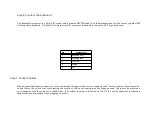
Step 7 Connect Cables,
Continued
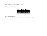
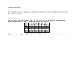
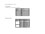
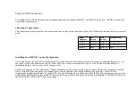
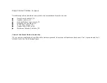
Onboard Adapters
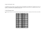
The AMIBIOS Power On Self Test (POST) routine checks the expansion slots for hard disk/floppy controller and serial/parallel
adapter cards. If a disk controller is found, the onboard IDE controller is automatically disabled. If a serial or parallel adapter
is found, the onboard serial or parallel port is disabled. Be sure to properly connect the cables to the berg connectors. Pin 1 of
each of the bergs is labeled "1". The wire leading to pin 1 on the cable usually has a colored stripe.
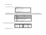
P4 Serial Port 1 (COM1)
and
P1 Serial Port 2 (COM2)
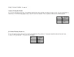
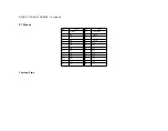
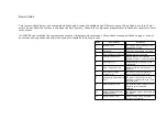
P4 is a 10-pin dual-inline berg. P1 is a 10-pin dual-inline berg. P1 and P4 connect a serial port receptacle to the motherboard.
These connectors provide an AT-compatible serial port interface. The connecting cable is a 10-pin double-row ribbon that
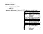
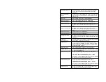
connects the motherboard to a male 9-pin D-sub connector fastened to the chassis. The serial port pinout is shown below.
Pin
Use
Pin
Use
1
Carrier Detect
6
Data Set Ready
2
Receive Data
7
Request to Send
3
Transmit Data
8
Clear to Send
4
Data Terminal Ready
9
Ring Indicator
5
GND
10
Key (N/C)
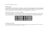
P5 Parallel Port for Printer
P5 is a 26-pin dual-inline berg. A 26-pin double-row ribbon cable connects P5 on the motherboard and a female 25-pin D-sub
connector fastened to the parallel port connector on the chassis.
Summary of Contents for 42 Series
Page 1: ...American Megatrends Inc Series 42 Mark V Baby Screamer 80386 Motherboard User s Guide ...
Page 2: ...MAN 642 Rev C 9 11 92 ...
Page 13: ......
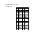
Page 35: ...A29 SA02 B29 5 A30 SA01 B30 OSC A31 SA00 B31 GND ...
Page 59: ......
Page 82: ......
Page 85: ...SRAM Locations ...

