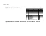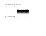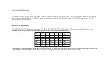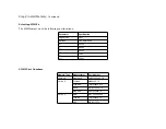
Step 1 Set Switch and Jumper Options
Set all user-configurable jumpers and switches, and install coprocessors before installing the motherboard in the chassis.
There is one user-configurable switch and ten jumpers.
SW1
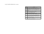
SW1 is an 8-position 2-bit DIP switch. See the graphic on page for the location of SW1.
Switch
Description
1
Diagnostics is used for manufacturing diagnostics. The
motherboard is shipped with this switch Off. The switch should
remain Off.
2
COL/MONO sets the type of video display adapter card in the
system. This switch is factory-set to Off, for a monochrome
display adapter (MDA™). Set On for a color graphics adapter
(CGA™). This switch has no effect on EGA® and VGA®
adapters.
3
Video Shadow. The video ROM segment beginning at C000h is
copied from ROM to faster RAM for faster video operation. This
switch is factory-set to On (Enable).
4
System BIOS Shadow. Similar to video shadow except the entire
system BIOS (64 KB in length) is shadowed. This switch is
factory-set to On (Enable).
5, 6, 7, 8
Memory configuration. Positions 5, 6, 7, and 8 configure the
system memory. See the section on configuring memory on page
.
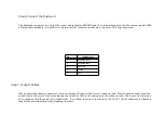
J22 COM1 IRQ Select
J22 is a three-pin single-inline berg. Short pins 2-3 to select IRQ4 for COM1 (default). Short pins 1-2 to select IRQ3 for COM1.
Summary of Contents for 42 Series
Page 1: ...American Megatrends Inc Series 42 Mark V Baby Screamer 80386 Motherboard User s Guide ...
Page 2: ...MAN 642 Rev C 9 11 92 ...
Page 13: ......
Page 35: ...A29 SA02 B29 5 A30 SA01 B30 OSC A31 SA00 B31 GND ...
Page 59: ......
Page 82: ......
Page 85: ...SRAM Locations ...


