Step 7 Connect Cables,
Continued
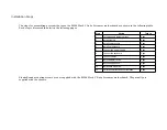
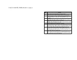
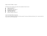
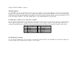
The following cables should be connected to the motherboard from the chassis:
●
Reset Switch cable to J12.
●
Speaker cable to J11.
●
External Battery connector to J2.
●
Keyboard Lock cable to J10.
●
Turbo LED cable to J15.
●
Connect DIAG LED to J13.
●
Hardware Deturbo Switch to J38.
Connect the Reset Button Connector
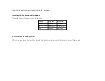
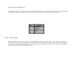
J12 is a two-pin single-inline berg. When this button is pressed, the system will perform a hard reset. Pin 1 is ground and Pin 2
is Hard Reset. See the following figure.
Summary of Contents for 42 Series
Page 1: ...American Megatrends Inc Series 42 Mark V Baby Screamer 80386 Motherboard User s Guide ...
Page 2: ...MAN 642 Rev C 9 11 92 ...
Page 13: ......
Page 35: ...A29 SA02 B29 5 A30 SA01 B30 OSC A31 SA00 B31 GND ...
Page 59: ......
Page 82: ......
Page 85: ...SRAM Locations ...

