AMI EZ-Flex Base Board User's Guide
31
Step 7 Connect the Cables,
Continued
Connect P014 Turbo Switch Connector
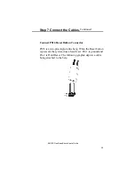
P014 can be connected to a front panel 2-position turbo
switch that allows the CPU speed to be altered via this front
panel pushbutton. When the button is in (closed), the
system operates at low speed. When the button is out
(open), the system operates at high speed. The keyboard
speed control overrides the front panel speed setting. P014
is a two-pin single-inline berg. Pin 1 is ground and Pin 2 is
Mode switch. See the berg connector on page
Error!
Bookmark not defined.
.
Connect P015 Turbo LED Connector
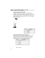
P015 can be connected to a front panel LED to reflect the
current CPU operating speed. The CPU speed can be
toggled from the keyboard by an OEM-specified (through
AMIBCP) keychord, such as <Ctrl> <Alt> <+> and <Ctrl>
<Alt> <-> (the default keystroke combinations). P015 is a
two-pin single-inline berg. The Turbo LED is lit when the
board is running at high speed. Pin 1 is LED Power (the
anode of the LED) and Pin 2 is Clock Speed (the cathode of
the LED). Pin 1 is labeled on the Base Board diagram on
page 16. See the berg connector on page
Error! Bookmark
not defined.
.
If after system boot, pressing <Ctrl> <Alt> <+> does not
light the turbo LED, the Turbo LED may not be connected
properly. Reverse the connection and try turbo mode again.
If the system still does not switch to turbo mode, the Turbo
LED may be defective.
Summary of Contents for 28 series
Page 1: ...American Megatrends Inc Series 28 EZ Flex Base Board User s Guide MAN 528 6 18 92 ...
Page 22: ...Chapter 4 Installation 16 ...
Page 55: ...AMI EZ Flex Base Board User s Guide 49 ...
Page 87: ...AMI EZ Flex Base Board User s Guide 81 ...
Page 103: ...AMI EZ Flex Base Board User s Guide 97 ...
Page 118: ...Appendix A EISA Configuration Worksheets 112 ...

