AMI EZ-Flex Base Board User's Guide
23
Step 4 Connect the Power Supply,
Continued
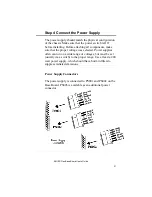
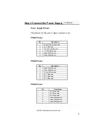
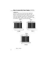
Power Supply Pinout
The pinouts for the power supply connectors are:
PS001 Pinout
Pin
Description
1
Power Good (Orange wire)
2
VCC (Red wire)
3
+12 Volts (Yellow wire)
4
-12 Volts (Blue wire)
5
Ground (Black wire)
6
Ground (Black wire)
PS002 Pinout
Pin
Description
1
Ground (Black wire)
2
Ground (Black wire)
3
-5 Volts (White wire)
4
VCC (Red wire)
5
VCC (Red wire)
6
VCC (Red wire)
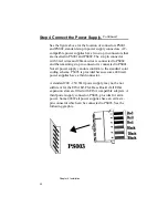
PS003 Pinout
Pin
Description
1
VCC (Red wire)
2
VCC (Red wire)
3
VCC (Red wire)
4
Ground (Black wire)
5
Ground (Black wire)
6
Ground (Black wire)
Summary of Contents for 28 series
Page 1: ...American Megatrends Inc Series 28 EZ Flex Base Board User s Guide MAN 528 6 18 92 ...
Page 22: ...Chapter 4 Installation 16 ...
Page 55: ...AMI EZ Flex Base Board User s Guide 49 ...
Page 87: ...AMI EZ Flex Base Board User s Guide 81 ...
Page 103: ...AMI EZ Flex Base Board User s Guide 97 ...
Page 118: ...Appendix A EISA Configuration Worksheets 112 ...


