Chapter 4 Installation
22
Step 4 Connect the Power Supply,
Continued
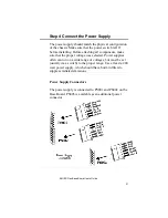
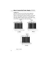
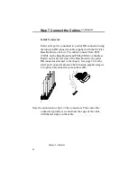
See the figure above for the location of connectors PS001
and PS002, standard six-pin power supply connectors. AT-
compatible power supplies have two six-pin connectors that
are inserted in PS001 and PS002. The six-pin connector
with 3 red wires and 2 black wires is connected to PS002
and the remaining six-pin connector is connected to PS001.
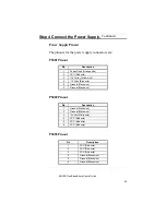
Not all power supply vendors conform to the standard color
coding scheme. PS003 is provided because some 400 watt
power supplies have a third connector.
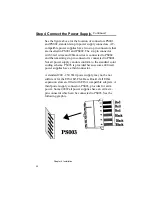
A standard 200 - 250 Watt power supply may not be not
sufficient for the EISA EZ-Flex Base Board if all EISA
expansion slots are filled with EISA compatible adapters. A
third power supply connector, PS003, provides for extra
power. Some 400 Watt power supplies have an extra six-
pin connector which can be connected to PS003. See the
following graphic.
Summary of Contents for 28 series
Page 1: ...American Megatrends Inc Series 28 EZ Flex Base Board User s Guide MAN 528 6 18 92 ...
Page 22: ...Chapter 4 Installation 16 ...
Page 55: ...AMI EZ Flex Base Board User s Guide 49 ...
Page 87: ...AMI EZ Flex Base Board User s Guide 81 ...
Page 103: ...AMI EZ Flex Base Board User s Guide 97 ...
Page 118: ...Appendix A EISA Configuration Worksheets 112 ...


