7. Maintenance
313
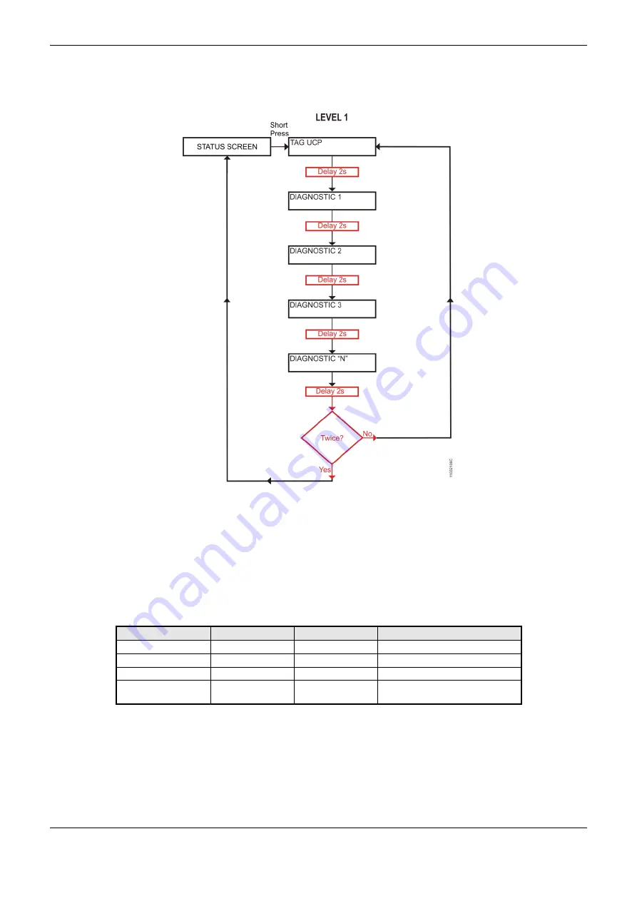
Figure 7-2 shows the complete process since the initial Touch. The conditions and times of CPU are
illustrated in smaller rectangles. Notice that the diagnostics may have more than one screen, that is,
the time in the block diagram is valid for each one of them.
Figure 7-2. CPU Diagnostics View
In order to stop the visualization process before its conclusion, perform a short touch on the
diagnostic switch, at any moment, or press the diagnostic switch from any I/O module connected to
the bus.
A long touch causes the CPU to enter in the navigation menu. See Informative Menu and of CPU’s
Configuration.
Table 7-1 shows the difference between the touch times (short, long and stuck button).
Touch
Minimum time
Maximum time
Indication condition
No touch
-
59.99 ms
-
Short touch
60 ms
0.99 s
Release
Long touch
1 s
20 s
Higher than 1s up to 20 s
Locked Switch
20,01 s
(
∞)
Diagnostics indication, see Table
7-4
Table 7-1. Tempo de One Touch
The diagnostics messages presented on Hadron Xtorm CPU graphic display are described in the
chapter Diagnostics via Variables, Table 7-3 and Table 7-4.
If any situation of stuck button occurs in one of the I/O modules, the diagnostic button of this module
will stop of the diagnostics indication on CPU graphic display. In this case, the CPU indicates that


