31
3 Operation
Alpha Technologies
3.4 Troubleshooting With the SID
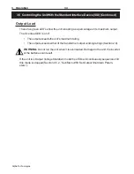
The SID’s Output Load LEDs have two functions:
• When the unit is operating normally, it serves to show the unit’s output loading.
• When the Service LED is on, the load LEDs are turned into a fault indicator for as long as
the Alarm Off button is pushed and held down.
See Section 5.2 for more troubleshooting information.
D
E
L D
E
L D
E
L D
E
L D
E
L
g
n
i
h
s
a
l
F
r
o
N
O
g
n
i
h
s
a
l
F
r
o
N
O
g
n
i
h
s
a
l
F
r
o
N
O
g
n
i
h
s
a
l
F
r
o
N
O
g
n
i
h
s
a
l
F
r
o
N
O
n
o
it
c
n
u
fl
a
M
n
o
it
c
n
u
fl
a
M
n
o
it
c
n
u
fl
a
M
n
o
it
c
n
u
fl
a
M
n
o
it
c
n
u
fl
a
M
n
o
it
c
A
n
o
it
c
A
n
o
it
c
A
n
o
it
c
A
n
o
it
c
A
d
a
o
l
r
e
v
O
d
a
o
l
r
e
v
O
d
a
o
l
r
e
v
O
d
a
o
l
r
e
v
O
d
a
o
l
r
e
v
O
N
ON
ON
ON
ON
O
.
e
v
it
c
a
y
ti
v
it
i
s
n
e
s
w
o
l
r
o
t
c
e
t
e
d
t
s
a
F
.
s
e
i
g
o
l
o
n
h
c
e
T
a
h
p
l
A
t
c
a
t
n
o
C
g
n
i
h
s
a
l
F
g
n
i
h
s
a
l
F
g
n
i
h
s
a
l
F
g
n
i
h
s
a
l
F
g
n
i
h
s
a
l
F
.
d
e
n
if
e
d
t
o
N
.t
i
n
u
s
i
h
t
n
i
d
e
s
u
t
o
N
%
0
0
1 %
0
0
1
%
0
0
1
%
0
0
1
%
0
0
1
N
ON
ON
ON
ON
O
.
e
r
u
t
a
r
e
p
m
e
t
t
n
e
i
b
m
a
h
g
i
H
.
g
n
i
k
r
o
w
e
r
a
s
n
a
f
e
h
t
fi
e
e
S
g
n
i
h
s
a
l
F
g
n
i
h
s
a
l
F
g
n
i
h
s
a
l
F
g
n
i
h
s
a
l
F
g
n
i
h
s
a
l
F
.t
l
u
a
f
L
L
P
.
s
e
i
g
o
l
o
n
h
c
e
T
a
h
p
l
A
t
c
a
t
n
o
C
%
5
7 %
5
7 %
5
7 %
5
7 %
5
7
N
ON
ON
ON
ON
O
.t
i
u
c
r
i
c
t
r
o
h
s
e
g
a
tl
o
v
t
u
p
t
u
O
*
.
d
e
ti
u
c
r
i
c
t
r
o
h
s
t
o
n
s
i
d
a
o
l
e
h
t
e
e
S
g
n
i
h
s
a
l
F
g
n
i
h
s
a
l
F
g
n
i
h
s
a
l
F
g
n
i
h
s
a
l
F
g
n
i
h
s
a
l
F
.
h
g
i
h
e
g
a
tl
o
v
t
u
p
t
u
O
*
.
s
e
i
g
o
l
o
n
h
c
e
T
a
h
p
l
A
t
c
a
t
n
o
C
%
0
5 %
0
5 %
0
5 %
0
5 %
0
5
N
ON
ON
ON
ON
O
.
e
r
u
li
a
f
M
O
R
P
E
E
d
r
a
o
b
r
e
w
o
P
d
l
u
o
h
s
d
n
a
s
n
o
it
c
n
u
fl
a
m
e
s
e
h
t
x
if
t
o
n
n
a
c
r
o
t
a
r
e
p
o
e
h
T
*
.
e
c
n
o
t
a
s
e
i
g
o
l
o
n
h
c
e
T
a
h
p
l
A
t
c
a
t
n
o
c
g
n
i
h
s
a
l
F
g
n
i
h
s
a
l
F
g
n
i
h
s
a
l
F
g
n
i
h
s
a
l
F
g
n
i
h
s
a
l
F
.
e
r
u
li
a
f
li
a
r
r
e
w
o
P
r
o
T
L
F
W
H
d
r
a
o
b
r
e
w
o
P
%
5
2 %
5
2 %
5
2 %
5
2 %
5
2
N
ON
ON
ON
ON
O
.t
l
u
a
f
y
r
e
tt
a
b
r
o
e
g
a
tl
o
v
r
e
v
o
y
r
e
tt
a
B
*
*
.
n
o
s
i
r
e
k
a
e
r
b
ti
u
c
r
i
c
y
r
e
tt
a
b
e
h
t
t
a
h
t
e
e
S
g
n
i
h
s
a
l
F
g
n
i
h
s
a
l
F
g
n
i
h
s
a
l
F
g
n
i
h
s
a
l
F
g
n
i
h
s
a
l
F
.t
s
e
t
fl
e
s
d
e
li
a
f
ti
n
U
*
*
.
y
r
e
tt
a
b
e
h
t
k
c
e
h
C
* After fixing the malfunction, these are cleared from the display panel by shutting down and restarting the unit.
** After fixing the malfunction, the unit automatically returns to Line Present mode, clearing the malfunction from the panel.
Figure 3.1
Fault Chart
TIP:
If the line present LED flashes, the utility line is unqualified and the unit will not start.
ALARM
OFF
MANUAL
START
OUTPUT LOAD
OVERLOAD
100%
75%
50%
25%
LINE PRESENT
LINE FAILURE
SERVICE
LOW BATTERY
WARNING
LOW BATTERY
SHUTDOWN
TEST
Procedure:
1
When the Service LED is on, press and
hold down the Alarm Off button.
2
The Output Load LEDs show a fault code.
See Figure 3.1 for the fault descriptions.
3
Fix the fault.
4
To clear some faults from the panel, you
may have to restart the unit. For others, the
fault is cleared by pressing the Alarm Off
button.
Troubleshooting Finished


