2 Installation
26
Alpha Technologies
2.8 Transformer Output Load Sharing (Continued)
2.8.2.2: Displaying the Output Current
TIP:
When using the display panels, you must calculate L1’s current as described
below.
Using the SID Display Panel:
The current is displayed via RS–232 as Output Current 1 and Output Current 2 (Section
4.4.3).
1
Use the menu to display Output Current 1 and Output Current 2.
2
The current in Winding 1 (Output Current L1) is the sum of Output Currents 1 and 2.
3
The current in Winding 2 is Output Current 2.
The Overload LED will flash if the total current in either winding exceeds its maximum
rating or if the total output in VA or Watts exceeds the unit’s maximum output.
Using the IID Display Panel:
1
Use the menu to display Output Current 1 and Output Current 2.
2
The current in Winding 1 (Output Current L1) is the sum of Output Currents 1 and 2.
3
The current in Winding 2 is Output Current 2.
Output
Terminal Block
L
N
230 VAC
A
230 VAC
Receptacle
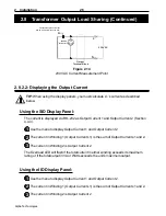
The total output current for
230 VAC units is measured at A.
Figure 2.14
230 VAC Current Measurement Point

