


2. INSTALLATION
13
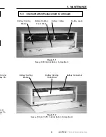
Site Preparation
Install the UPS in a well-ventilated, dust-free environment. Do not mount it on any
surface unable to fully support its weight.
Install the UPS near the equipment to be protected. The AC line socket and the
output receptacles must be easily accessible in case of an emergency.
Utility Circuit Breaker
The UPS should be installed on a dedicated circuit with a properly sized circuit
breaker to protect the UPS from short circuits or over-currents. Check the UPS
nameplate for the appropriate current rating.
For UPS's equipped with terminal blocks, mark the circuit breaker controlling the
power going to the UPS for emergency disconnection from utility line AC power.
Grounding
Many older facilities may have an electrical system that is incapable of supporting
current grounding requirements. A qualified electrician should inspect the existing
wiring in the building prior to installation to verify proper grounding. Use the
external ground lug on the UPS's rear panel if required.
Standby Generators
The UPS is equipped with a frequency sense circuit, along with a frequency
synchronization circuit, to optimize operation with most standby generators. Prior
to installation, compare the output voltage of the generator to the voltage
requirements of the UPS (see the UPS nameplate label).
By switching the UPS to Generator Mode, the acceptable ranges of input voltage
and frequency can be broadened to accommodate fluctuations inherent to
generator power.
Alpha Technologies recommends using a generator equipped with electronic
speed and voltage control. Generators equipped with mechanical governors can
cause the UPS to run continuously in On Battery mode due to the unstable
frequency of the generator. The generator should produce less than 10%
voltage total harmonic distortion (THD).
2.1
Pre-installation
4. COMMUNICATION
48
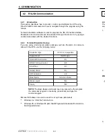
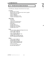
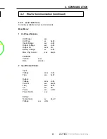
4.2
RS-232 Communication (Continued)
4.2.9
Calibration
Calibration allows you to customise the UPS detection and warning
characteristics. Normally, these factory settings do not have to be changed.
CAUTION: Improper calibration parameter values may cause permanent
damage to the UPS. The calibration must be done by well trained
personnel only. Parameter values are relative numbers that only make
sense when viewed through the UPS control system. Contact Alpha
Technologies before making any adjustment.
Slow Detect Hi Lmt
Decreasing this value makes the UPS more sensitive to a slow, high
amplitude line disturbance (sustained overvoltage) by lowering the
overvoltage detection level.
NOTE: The Slow Detect Hi Hys Ref should also be adjusted by the same
amount.
Slow Detect Lo Lmt
Increasing this value makes the UPS more sensitive to a slow, low
amplitude line disturbance (brownout) by raising the brownout detection
level.
NOTE: The
Slow Detect Lo Hys Ref should also be adjusted by the same
amount.
Slow Detect Lo Hyst
Increasing this value raises the voltage level where the UPS resumes On
Line
mode after a line disturbance has been corrected.
Slow Detect Hi Hyst
Decreasing this value lowers the voltage level where the UPS resumes
On Line
mode after an overvoltage condition has been corrected.
Slow Detect Boost High
Increasing this value raises the re-transfer voltage from Boost mode to
On Line
mode.
Slow Detect Boost Low
Increasing this value raises the transfer voltage from On Line
mode to
Boost mode.
Bat Charge Current
Increasing this value increases the battery charging current.


