2. INSTALLATION
23
2.5
Connecting the UPS
2.5.1
Connecting a UPS Equipped with Plugs and Receptacles
WARNING: Total Earth ground leakage currents of loads connected to the UPS
are not to exceed 3.1 mA.
1.
Connect the UPS to utility line AC power.
2.
If required, connect the external battery (EBP) to the UPS using the
connector cable.
3.
Start and test the UPS as shown in Section 3.2.
Figure 2.11
Rear Panel Connections
External Battery
Pack Connector
External
Battery Pack
(EBP)
AC Output
Receptacles
Communication/
Alarm Connector
AC Line
Power Cord
Connector
External Battery
Pack Cable
3. OPERATION
38
3.5
Front Panel Indicators and Controls (Continued)
9.
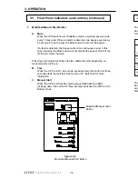
Hot Swap Mode
In Hot Swap mode, the internal batteries can be replaced without
switching off the UPS.
A.
Conditions to switch the UPS into Hot Swap mode are:
•
The UPS must be in On Line
or Boost mode.
•
The UPS must NOT be in On Battery
mode.
B.
To switch into Hot Swap mode, simultaneously press and hold both
the Mute and % Batt buttons for more than three seconds.
C.
In Hot Swap mode:
•
The charger is disabled.
•
The inverter is disabled.
•
The four lower LEDs are flashing.
The On Line and Boost modes are inactive. The UPS does not
switch between Boost, On Line, or On Battery
mode even if the
utility line conditions change.
D.
To exit Hot Swap mode after installing the internal batteries,
simultainously press and hold the Mute and % Batt buttons for at
least three seconds. After exiting Hot Swap mode, the four lower
LEDs stop flashing and the UPS resumes normal operation. See
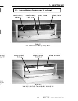
Section 5.3, “Internal Battery Replacement” for internal battery
replacement procedures.
10. Generator Mode
Press the Mute and % Load buttons simultaneously for 3 seconds while
the UPS is in On Line mode. The On Line LED is ON and the Test LED
flashes. To switch to Generator mode, press the % Batt button within 30
seconds and the On Battery LED comes ON. If the % Batt button is not
pressed within 30 seconds, the UPS returns to On Line mode.


