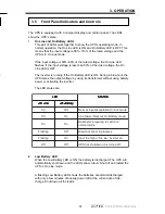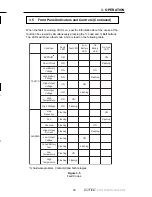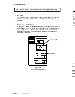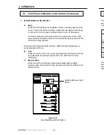
2. INSTALLATION
22
2.4
Rack Mounting
1. Mount the multipurpose brackets on the sides of the UPS cabinet. The
brackets can be mounted in the centre of the chassis or flush with the front
panel.
NOTE: By changing the orientation of the multipurpose bracket, the UPS
can be mounted in a 19 or 23 inch rack. However, the standard multipur-
pose bracket is not strong enough to be mounted flush with the front panel
in the 23 inch rack configuration. A thicker multipurpose bracket is available
from Alpha Technologies for that purpose.
.
Figure 2.10
Rack Mounting
2. Lift the UPS into position and secure the brackets to the rack.
WARNING: The unit is heavy! Use proper lifting techniques.
3.
If an external battery pack (EBP) is being installed, mount it to the rack in
the same way as the UPS module. Connect the EBP to the UPS using the
EBP connector cable.
4.
Connect the UPS as shown in Section 2.5.
Multipurpose
Bracket For
Rack Mounting
4. COMMUNICATION
39
4.1
Interface Port
The UPS is equipped with a DE–9 female connector for remote communica-
tion. When linked to a PC with a terminal emulation package, the PC can
monitor, control, and calibrate the UPS using RS–232 ASCII commands.
4.1.1
Pin Assignments
•
Pin–1: Inverter Shtdwn
The UPS shuts down the inverter (no output voltage) when a RS–232
high level (+7 to +15 volts) signal is applied to Pin–1 for 2.5 seconds.
The UPS responds to this signal only when in On Battery
mode.
•
Pin–2: Not Connected
•
Pin–3: Line Fail,
Line Fail Alarm (N.O.), 10 mA maximum
Along with COM (Pin–4), this opto-isolated open collector pin
simulates a relay contact closure whenever the AC line is out of
tolerance (e.g. On Battery
mode except in Test mode).
•
Pin–4: COM, Common for Pin 3 and 5
This is the common signal for Line Fail and Low Battery alarm signals.
This pin is not internally connected to the logic ground. If required, the
connection to the logic ground should be provided externally.
•
Pin–5: Low Batt, Low Battery Alarm (N.O.), 10 mA maximum
This opto-isolated, open-collector pin and COM (Pin–4) simulates a
relay contact closure whenever the battery runtime is low.
•
Pin–6: +V, +7V to +12V, 20 mA maximum
This pin provides a positive voltage whenever the UPS is powered up.
The positive voltage can be used to either shutdown the inverter by
placing a switch/relay contact between Pin–6 and Pin–1 (Shutdown) or
to provide a pull up voltage for the Line Fail and Low Batt signals.
•
Pin–7: Tx, RS-232 Transmit
•
Pin–8: Rx, RS-232 Receive
•
Pin–9: GND, logic GND for RS-232 and +V.


