2. INSTALLATION
14
2.2
Tower Configuration Installation
2.2.1
UPS Installation
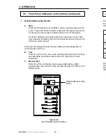
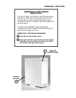
1. Install the four rubber feet on the correct side of
the cabinet. For proper ventilation, the front
panel vent hole must be on the bottom when the
UPS is standing on its rubber feet.
Requires
Phillips Screwdriver
Figure 2.1
Rubber Feet
2. Install the multipurpose bracket as a seismic bracket on both sides of the
UPS.
Figure 2.2
Seismic Bracket
3.
Stick the adhesive side of the horizontal layout overlay label over the control
and display panel to make reading the control and display panel easier.
Make sure that the label is properly aligned.
4.
Connect the UPS as shown in Section 2.5.
Rubber
Feet
Multipurpose
Bracket as a
Seismic Bracket
4. COMMUNICATION
47
4.2
RS-232 Communication (Continued)
Volt Amps
The apparent output power of the UPS is calculated by multiplying the
output voltage by the output current. The total UPS output VA may not
equal the sum VA drawn from the connected equipment. This is due to
different power factor rating for each piece of equipment.
Power in Watts
The real output power of the UPS is calculated in Watts. This is equal to the
sum of the real output power for all equipment connected to the UPS.
Power Factor
The ratio of true power (power actually consumed) to apparent power
(simple product of voltage and current) at the input of the UPS expressed
as a decimal (e.g., 0.89).
4.2.7
Battery
Battery Temperature
Displayed in degrees C, Ambient Temperature is measured inside the UPS
in the vicinity of the battery compartment.
Battery Voltage
Voltage indicates the average DC voltage of UPS batteries.
4.2.8
Maintenance
Maintenance allows you to start the test mode and shut down the output.
Battery test options
A self test can be initiated or cancelled by selecting this menu. The test
duration can be set in steps of 0.5 seconds. The default is 120 steps which
equals 60 seconds.
Output Shutdown
The output of the unit can be turned off by sending a command via the RS–
232 port using a computer or terminal. The shutdown delay can be set in
steps of 0.5 seconds. The default is 0. The Test LED flashes when a delay
is set and a UPS Output Shutdown is pending.
Inverter On/Off
Switches the inverter on or off. This option is used when the unit is in the
On Battery
mode to prevent a deep battery discharge. The UPS does not
respond to this command when it is not in On Battery
mode. Inverter Off
delay can be set in steps of 0.5 seconds. The default is 0. The Test LED
flashes when a delay is set and a UPS
Inverter Off state is pending.

