3. OPERATION
26
3.1
Operating Modes
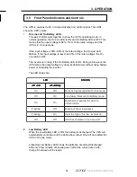
On Line
Mode
This is the normal mode of the UPS with the On Line LED ON, the On Battery
LED OFF, and the batteries being charged.
Boost Mode
In this mode, the UPS automatically uses a step-up transformer to increase the
output voltage by up to 12% without using the batteries or inverter when the
input voltage falls below a preset limit.
On Battery Mode
The UPS automatically switches into this mode if the utility line AC power:
•
Voltage is outside acceptable limits.
•
Voltage fluctuates too rapidly.
•
Frequency varies more than
+
/
-
3 Hz of rated frequency.
Or:
•
The operator presses the Manual Start button on the Display and Control
panel while the UPS is in Stand-by mode.
In this mode, the UPS's Display and Control Panel’s On Battery LED is ON and
the On Line LED is OFF. The batteries and inverter circuit supply AC power to
the loads. The UPS automatically returns to On Line mode when the utility line
AC voltage or frequency returns to normal conditions.
The UPS's On Battery Mode has three different states as the battery is
discharged. See Figure 3.1, “Low Battery Mode States.”
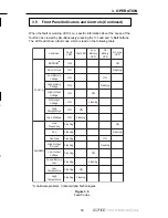
1) Low Battery Warning State
The UPS automatically switches into this state when it is in On Battery mode.
The battery has enough power to keep the loads running, but it is almost
discharged and cannot supply the loads for much longer.
In this state, the Display and Control Panel’s Low Battery LED is flashing. The
operator should perform an emergency shutdown of the loads before the
battery is completely discharged.
2) Low Battery Shutdown State
The UPS automatically switches into this state when it is in On Battery mode
and the battery is discharged to a level where it cannot provide backup power
to the loads, but it can supply power to the UPS’s internal electronics.
In this state, the Display and Control panel’s LED’s are sequentally flashing.
This indicates the UPS is in Standby mode, providing no power to the loads,
but its electronics are still active. It stays in this state until utility line AC power
is available. Then the Display and Control Panel’s On Line LED turns on, utility
line AC power is provided to the loads, and the UPS starts recharging the
battery.
3. OPERATION
35
3.5
Front Panel Indicators and Controls (Continued)
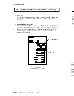
6.
Battery Charge Indicator
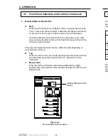
Pressing the % Batt button shows the approximate charge of the battery.
The LEDs show the percent battery voltage between fully charged and
discharged levels.
NOTE: Batteries that cannot be fully charged should be serviced or
replaced. Test the runtime annually using the procedure in Section
5.2, “Runtime Testing” to ensure that the batteries can hold an
acceptable charge.
Figure 3.7
Battery Charge Indicator Button
% Battery Button


