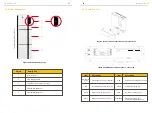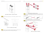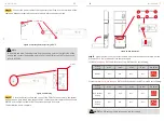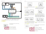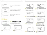
Step12
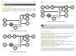
Fix the wall bracket with the hexagonal bolts (tool: SW13 screwdriver, torque:
30 N.m) to the wall and fix the battery mounting plate with M6 nuts. The battery
assembly is now complete.
Step13
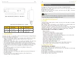
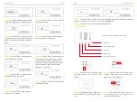
Please make AC cables on site.
Step13-1
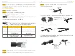
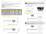
Please follow the AC cable requirements below.
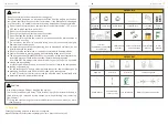
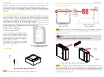
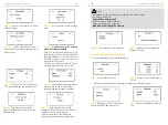
For backup AC cables the stripping method is as following:
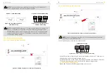
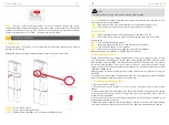
a.
Parts are equipped with cables
b.
Crimp the wire according to the position shown, tighten the screw torque0.8±0.1N·m.
c.
The plastic core is screwed into the body
d.
Put the sealing body into the main body groove, and then tighten the lock nut to the
main body with a wrench. Torque 2.0±0.3 N·m
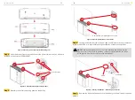
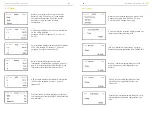
Step13-2
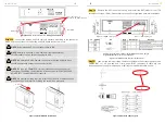
Assemble the AC connector and connect the conductor to the AC connector
Step13-3
Ensure that all conductors are securely connected to the AC connector.
Step13-4
Plug the AC connector into the jack for the AC connection.
For grid AC cables the stripping method is as following:
Strip the insulation sheath of the three-core AC cable for about. 30mm. Strip
L, N and PE cables for 6-7mm respectively.
Strip the insulation sheath of the three-core AC cable for about 35mm. Cut L
and N cable for 5mm. Strip L, N and PE cables 6-7mm for respectively to
make sure X-length is 5mm longer than Y-length of L/ N cable.
Insert the cables into the
corresponding Pin holes and
tighten the screws with the
screwdrivers.
INSTALLATION
INSTALLATION
External diameter
Conductor cross-section
approx.6.5mm
2.5 mm² to 4 mm²
8 mm to 14 mm
Stripping length of the
insulated conductors
Stripping length of the outer
sheath of the AC cable
approx. 30 mm (Backup)
approx.30mm (Grid L and N)
approx.35mm (Grid PE)
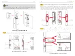
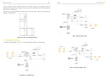
2.2.2 Inverter Installation
Main part
Lock nut
Line male
Male
Female
PE
L
N
Sealing body
Screw the
body onto the
plastic core
Put the
sealing body
into the main
body and lock
the lock nut
with a wrench
Female
Female
Female
17
18
Value
Description
Object
A
B
C
D


