Installation & Systems Manual RUBIDIUM SERIES
Page 39
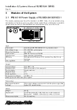
3.4
PD
: Power Distribution
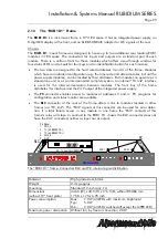
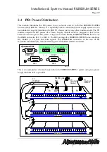
This module distributes the DC power to any external units or to further RUBIDIUM SERIES
frames (except RUB D1 chassis). It is especially used in redundant power supply systems. It can
be installed at any slot (location) of a RUB H1 chassis just as any other module would. The PD
module outputs the DC power of a Power Supply module which is plugged in this frame.
External units can get its DC power using the terminal blocks; RUBIDIUM SERIES frames use
the DSUB connector RLC 1 or RLC 2. The RLC pinning of a RUBIDIUM SERIES frame combines
DC, RS485 (= TC_link) and FAIL signals. The RS485/FAIL connector at the rear of PD
separates the RS485 (TC_link) and FAIL signals of the RLC1/RLC2 connectors.
1
RS485 / FAIL
RLC 1
AlVelte
RLC 2
1
1
+ - + -
+ - + -
DC OUT
PD_01
1 2 3 4
1 2 3 4
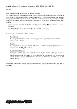
This is an example for a fail-safe operation of a RUBIDIUM SERIES 1 system using two power
supply modules “PS” in parallel.
AlVelte
R U B I D I U M SERIES 1
OPER
ERROR
SET
SIGNAL
OPER
ERROR
SET
SIGNAL
OPER
ERROR
SET
SIGNAL
OPER
ERROR
SET
SIGNAL
PD2_02
RLC
AlVelte
R U B I D I U M SERIES 1
OPER
ERROR
SET
SIGNAL
OPER
ERROR
SET
SIGNAL
OPER
ERROR
SET
SIGNAL
OPER
ERROR
SET
SIGNAL
RLC
RS485/TC_link
FAIL
AlVelte
R U B I D I U M SERIES 1
OPER
ERROR
SET
SIGNAL
OPER
ERROR
SET
SIGNAL
OPER
ERROR
SET
SIGNAL
OPER
ERROR
SET
SIGNAL
RLC
PS
PS
PD
RLC
RS485
FAIL
~
~
Primary Circuit 1
Primärkreis 1
Primary Circuit 2
Primärkreis 2
1:1
>= AWG24

