Summary of Contents for RUBIDIUM

Page 1: ...Installation Systems Manual Version 4 1 September 26 2012 RUBIDIUM SERIES Universal Video Data Processor...

Page 2: ......

Page 3: ...ocal Area Network 19 1 3 5 Local Serial Interfaces 19 1 4 MODULE AND SYSTEM CONFIGURATION 20 1 4 1 Overview 20 1 4 2 Unique Identification of a Module and a Frame 20 1 4 3 Installation of a Module 21...

Page 4: ...TIONS 52 3 18 XI DIGITAL VIDEO FOR SPECIAL APPLICATIONS 53 3 19 GT MASTER TIME CODE GENERATOR 54 3 20 GI MASTER IRIG B GENERATOR 55 3 21 GL LTC MTD GENERATOR 56 3 22 GT GI GL STANDARD OPTIONS 57 3 23...

Page 5: ...on the Module 79 4 1 8 The System Tab Module Identification Reset SNMP Fan Control 80 4 2 THE RUBIDIUM SERIES HTTP SERVER 82 4 2 1 Overview Connecting the IE Module 82 4 2 2 IP Configuration 83 4 2 3...

Page 6: ...23 2005 S1 frame 3 3 June 16 2006 New modules PQ VL HT HV T1 chassis Chapter Software Tools for RUBIDIUM SERIES revised 3 4 November 22 2006 Chapter 2 1 5 fan module 4 1 8 and 4 2 6 system revised 3...

Page 7: ...brand and product names mentioned herein are used for identification purposes only and are trademarks or registered trademarks of their respective holders Information in this publication replaces all...

Page 8: ...defective product to Alpermann Velte please notice the Shipping Information given below This warranty shall not apply to any defect failure or damage caused by abuse misuse improper use negligence acc...

Page 9: ...nn Velte dealer Ensure that all packaging material is removed from the product and its associated components before installing the unit Products returned to Alpermann Velte for servicing or repair sho...

Page 10: ...ions Heed all warnings Follow all instructions Safety Terms and Symbols Terms and Symbols in this manual WARNING Warning statements identify conditions or practices that could result in injury or loss...

Page 11: ...not apply more than 264Vrms between the supply conductors or between either supply and ground A protective ground connection by way of the grounding conductor in the power cord is essential for safe...

Page 12: ...ient air circulation can be maintained Good air circulation is essential to prevent internal heat build up do not block any ventilation openings Do not expose the unit to direct sun light or any other...

Page 13: ...ccumulating in the apparatus acts as an insulating blanket preventing proper cooling and possibly causing overheating and component breakdown Under high humidity conditions accumulated dust can also p...

Page 14: ...areas that have a floor or work surface covering capable of generating a static charge Also nothing capable of generating or holding a static charge should be allowed in the work area 3 Handle ESD sen...

Page 15: ...Installation Systems Manual RUBIDIUM SERIES Page 15 A6 EC Declaration of Conformity...

Page 16: ...ot for RUB1 D1 which enables operation without a power supply module by using external power supply It is also possible to supply power from one internal power supply module in one frame to another fr...

Page 17: ...nnector at the frame provides the interface for the configuration of a module With the aid of our configuration software each module can be addressed and can receive a user selectable configuration Ch...

Page 18: ...1 F r a m e 2 Pin assignment of the 9 pins DSUB female connector RLC Pin Description 1 FAIL_A 2 TC_link RS485 TR 3 TC_link RS485 TR 4 FAIL_B 5 6 7 GND signal ground 8 9 Nominal 24 VDC 3 A maximum Not...

Page 19: ...le this pin serves as the voltage input Having a frame with at least one power supply module this pin can be used to supply voltage to another frame In this case no external voltage output of a Non Ru...

Page 20: ...Identification of a Module and a Frame An individual hard wired address is assigned to the module by the position within the frame Address 1 unit 1 position most left looking at the front side of the...

Page 21: ...cription of the software tools in this manual If you have further questions please contact your local dealer or Alpermann Velte directly 1 4 4 Update Most of the RUBIDIUM SERIES modules can easily get...

Page 22: ...assis The RUB1 S1 chassis was designed to house one rear loading RUB1 module in 19 1RU space RLC PC KEY KEY KEY KEY ID Alpermann Velte AC R U B 1 P E A C D C A d a p t e r Rub S1 The RUB1 T1 chassis w...

Page 23: ...ermore it has the FAIL and TC_link signals The RUB1 PE power supply unit can be plugged directly to this connector The FAIL signals can be used for error detection If a total failure occurs in the mod...

Page 24: ...ame offers a link to modules located in other frames via TC_link The FAIL signals at this connector can be used for error detection If a total failure occurs in any module in one frame the FAIL contac...

Page 25: ...he frame distributes this interface and the 24 V output of the integrated power supply The PC connector enables access to modules at addresses 3 and 4 PC programs for configuration and status monitor...

Page 26: ...r at the rear of the frame Red LED OPER at the front indicates that the module is operating Overview of the main features of this module Power Supply The integrated AC DC converter delivers approximat...

Page 27: ...C programs for configuration and status monitor are available The RLC connector at the rear of the frame combines the TC_link interface which enables communication to modules located in further chassi...

Page 28: ...les Failure relay connected to the FAIL_A and FAIL_B pins of the RLC connector at the rear of the frame Red LED OPER at the front indicates that the module is operating The 8 digit display 7 segment L...

Page 29: ...tain the cover plate for possible future use Remove the module from its anti static packing material Hold the module by the edges or the rear plate please do not touch the electronic components strip...

Page 30: ...protruding tab that needs to be slightly pressed to the right rear1_06 Alpermann Velte Now pull the module out of the slot Keep the anti static packing material original packaging material or adequate...

Page 31: ...2 3 2 The contacts of the fail relay are normally open during operation but close if this module or the fan has a failure The contacts are in parallel with the fail relays of all modules plugged into...

Page 32: ...ar screws and then fold down the front plate The RUB3 H3 frame usually comes complete with the RC module plugged at slot 1 This module with its two RLC connectors offers a link to modules located in o...

Page 33: ...s strip conductors or pins Retain the packing material for possible future use ATTENTION Observe precautions for handling electrostatic sensitive devices See Electro Static Discharge ESD Precautions a...

Page 34: ...module Unscrew both the collar screws Now pull the module out of the slot Keep the anti static packing material original packaging material or adequate pack aging ready Hold the module by the edges or...

Page 35: ...In a system of one or two frames all the switches should be set to position ON terminated In a system of more than two frames the switches of the first and the last frame should be set to position ON...

Page 36: ...ltage range 90 264 VAC auto ranging Power line frequency 47 63 Hz Input current 800 mA maximum at 90 VAC Inrush current 50 A maximum 264 VAC Efficiency 86 typical at 75 load 25 C nominal line after 5...

Page 37: ...nge 90 264 VAC auto ranging Power line frequency 47 63 Hz Input current 800 mA maximum at 90 VAC Inrush current 50 A maximum 264 VAC Efficiency 86 typical at 75 load 25 C nominal line after 5 mins war...

Page 38: ...voltage range 90 264 VAC auto ranging Power line frequency 47 63 Hz Input current 800 mA maximum at 90 VAC Inrush current 50 A maximum 264 VAC Efficiency 86 typical 75 load 25 C nominal line after 5 m...

Page 39: ...signals The RS485 FAIL connector at the rear of PD separates the RS485 TC_link and FAIL signals of the RLC1 RLC2 connectors 1 RS485 FAIL RLC 1 Alpermann Velte RLC 2 1 1 DC OUT PD_01 1 2 3 4 1 2 3 4 Th...

Page 40: ...Format Refer to VIDEO IN Connector BNC IEC169 8 75 VITC output According to ANSI SMPTE 12M 1 2008 LTC input Format According to ANSI SMPTE 12M 1 2008 Connector Balanced signals LTC_IN_A and LTC_IN_B...

Page 41: ...IN Format CVBS analogue video signal PAL 625 50 NTSC 525 60 Connector BNC IEC169 8 75 VITC input According to ANSI SMPTE 12M 1 2008 Video output LOOP OUT Format Pass through output of VIDEO IN Connect...

Page 42: ...ules Option S O Time code offset features for AT This option combines AT and a control unit TCU to a system which handles time code offset applications in an easy way The TCU control unit is used to e...

Page 43: ...nt DOWN counters are available Operating manual AI DI XI Modules Option C D Daytime inserter An external reference GPS DCF77 delivers a pulse per second PPS and time date via serial interface The modu...

Page 44: ...tal video according to ANSI SMPTE 259M Connector BNC IEC169 8 75 Video time codes D VITC SMPTE 266M 1994 ATC SMPTE 12M 2 2008 LTC input Format According to ANSI SMPTE 12M 1 2008 Connector Balanced sig...

Page 45: ...259M Connector BNC IEC169 8 75 Video time codes D VITC SMPTE 266M 1994 ATC SMPTE 12M 2 2008 Video output LOOP OUT Format Serial digital video according to ANSI SMPTE 259M Connector BNC IEC169 8 75 Vid...

Page 46: ...dules Option S O Time code offset features for DT This option combines DT and a control unit TCU to a system which handles time code offset applications in an easy way The TCU control unit is used to...

Page 47: ...nt DOWN counters are available Operating manual AI DI XI Modules Option C D Daytime inserter An external reference GPS DCF77 delivers a pulse per second PPS and time date via serial interface The modu...

Page 48: ...time codes D VITC SMPTE 266M 1994 ATC SMPTE 12M 2 2008 LTC input Format According to ANSI SMPTE 12M 1 2008 Connector Balanced signals LTC_IN_A and LTC_IN_B Via 3 pin XLR female according to IEC 268 1...

Page 49: ...D or ANSI SMPTE 259M SD Connector BNC IEC169 8 75 Video time codes D VITC SMPTE 266M 1994 ATC SMPTE 12M 2 2008 Video output LOOP OUT Format Same as video input Connector BNC IEC169 8 75 Video output V...

Page 50: ...D VITC SMPTE 266M 1994 ATC SMPTE 12M 2 2008 LTC input Format According to ANSI SMPTE 12M 1 2008 Connector Balanced signals LTC_IN_A and LTC_IN_B Via 3 pin XLR female according to IEC 268 1 Via 2 pins...

Page 51: ...2M SD SMPTE 259M Connector BNC IEC169 8 75 Video time codes D VITC SMPTE 266M 1994 ATC SMPTE 12M 2 2008 Video output LOOP OUT Format Same as video input Connector BNC IEC169 8 75 Video output VIDEO OU...

Page 52: ...dules Option S O Time code offset features for XT This option combines XT and a control unit TCU to a system which handles time code offset applications in an easy way The TCU control unit is used to...

Page 53: ...perating manual AI DI XI Modules Option C D Daytime inserter An external reference GPS DCF77 delivers a pulse per second PPS and time date via serial interface The module decodes these data calculates...

Page 54: ...to ANSI SMPTE 12M 1 2008 Free run accuracy all output signals TCXO Temperature stability 1 ppm Aging typical 1 ppm year LTC output Format According to ANSI SMPTE 12M 1 2008 Connector Balanced signals...

Page 55: ...RD 200 98 amplitude modulated carrier signal with 1 kHz carrier frequency Connector Balanced signals IRIG_OUT_A and IRIG_OUT_B via 2 pins of the IRIG connector DSUB female and RJ45 Output impedance 50...

Page 56: ...ectors DSUB9 female and RJ45 jack Output impedance 50 Signal level adjustable balanced use from 17 dBu 0 31 Vp p to 13 dBu 9 8 Vp p unbalanced use from 23 dBu 0 16 Vp p to 7 dBu 4 9 Vp p Free run accu...

Page 57: ...l data and a pulse per second PPS Using an external IRIG B instead requires this option L Operating manual GT GL GI Modules Option I M Impulse telegram output to control analogue clocks for GT GL GI W...

Page 58: ...p bi level and tri level sync signals Signal level 1 V 6 dB SYNC Signal 10 MHz Format 10 MHz sinusoidal Signal level 0 8 5 0 Vpp 4 x CLOCK OUT Connector BNC IEC169 8 75 in parallel to RJ45 CLOCK OUT O...

Page 59: ...TSC 525 60 480i p 576i p 720p 1080i p bi level and tri level sync signals Signal level 1 V 6 dB SYNC Signal 10 MHz Format 10 MHz sinusoidal Signal level 0 8 5 0 Vpp 2 x VIDEO OUT Connector BNC IEC169...

Page 60: ...n Example 1 VIDEOOUT VIDEO IN LOOPOUT RUB GT Generator Timecode GPI B GPIA REF IN MTD MTD OUT_2 OUT_1 INPUT 1 1 OUT_4 OUT_3 1 1 1 RUB VD Distribution remote PC or Server Connecting 2 WireSlaveClocks O...

Page 61: ...ated carrier signal with 1 kHz carrier frequency balanced signals Input impedance 18 k Signal level 100 mVp p 5 Vp p auto ranging LTC or IRIG output Format According to signal input balanced Signals O...

Page 62: ...plitude range 0 2 2 5 Vpp signal input at 75 Signal outputs Connector BNC IEC169 8 75 Output impedance 75 Gain 1 1 GPI_1 to GPI_7 outputs indicating failures Output specification Open Collector output...

Page 63: ...to control Alpermann Velte analogue clocks Alpermann Velte OUT 3 OUT 1 GPI IN 8 1 8 1 8 1 8 1 OUT 2 VTR IN LOOP 1 8 1 8 1 8 OUT 4 1 8 LTC input Format according to ANSI SMPTE 12M 1 2008 balanced Sign...

Page 64: ...le allows the selection between distributing the IN1 signal to both outputs or distributing IN1 to OUT1 and IN2 to OUT2 This way it is possible to directly connect to a GT or GL or SL module with the...

Page 65: ...T LINK ACT RESET Operating voltage 12 30 VDC Power consumption Version 1 2 7 W Version 2 1 8 W Weight 0 3 kg approx Mechanical Circuit board W x D 100 x 160 mm 3 94 x 6 30 inch Rear panel RUB H1 103 x...

Page 66: ...TTL pulse width 200 ms TXD Time and date serial telegram Meinberg Standard RS232 BATT IN RJ 45 Back Up Power 12 to 30 VDC input GPI A RJ 45 GPI_1 GPI_4 General Purpose Interface programmable outputs...

Page 67: ...Vpp 75 Connector BNC IEC169 8 75 50 on request REF OUT RJ 45 PPS Pulse per second TTL pulse width 200 ms TXD Time and date serial telegram Meinberg Standard RS232 BATT IN RJ 45 Back Up Power 12 to 30...

Page 68: ...Format ANSI SMPTE 12M 1 2008 balanced Signal level 100 mVp p 5 Vp p auto ranging Input impedance 18 k Frequency 19 33 frames s SERIAL IN Serial time date data string TELEGRAM IN Impulse telegram LTC...

Page 69: ...T VITC IN 1 VITC IN 2 REF OUT GPI OUT REF IN REF OUT 8 1 8 1 1 8 1 8 VITC IN 2 x BNC Video format CVBS analogue video signal PAL 625 50 NTSC 525 60 Signal level 1 V 6 dB at 75 VITC According to ANSI S...

Page 70: ...T REF IN 1 10MHZ IN 1 10MHZ IN 2 10MHZ OUT 8 1 8 1 1 8 1 8 10 MHz IN 4 x BNC 10 MHz DC range 5 V Input impedance 2 k Signal specifications Frequency range 10 MHz 5 amplitude range 0 6 2 5 Vpp 10 MHz O...

Page 71: ...plitude modulated carrier signal with 1 kHz carrier frequency balanced signals Signal level 100 mVp p 5 Vp p auto ranging Input impedance 18 k SERIAL IN Serial time date data string TELEGRAM IN Impuls...

Page 72: ...e DARS OUT 8 1 8 1 1 8 1 8 REF GPO CLOCK IN 2 8 1 1 8 CLOCK IN 1 DARS IN 1 CLOCK OUT 1 2 3 4 CLOCK IN 2 x RJ45 Connector RJ45 suited for direct connection to CLOCK OUT of RUB GW Signal 4 word clock si...

Page 73: ...l time requirements can be checked as well VIDEOIN 1 REF OUT GPO Alpermann Velte REF IN REF OUT VIDEOIN 2 VIDEOOUT A B 8 1 8 1 1 8 1 8 VIDEO BNC IEC169 8 75 Video format Composite analogue video signa...

Page 74: ...e is included on the supplied CD Service Software and Updates or can be downloaded from the service section of our web site http www alpermann velte com serv_e software_e software_e html Rubidium Conf...

Page 75: ...the PC connector on the RUBIDIUM SERIES chassis If the Rubidium s PC connec tor is being used for other applications temporarily disconnect this cable while using this set up program USB Alpermann Vel...

Page 76: ...s the type of chassis e g The following chassis are presently available D1 H1 H3 S1 T1 Module Please select the module that you would like to configure according to module s position front view left t...

Page 77: ...ermine whether the function in the module is activated or deactivated and whether a set up of that specific function is allowed or not Click on the applicable Edit and or Use check boxes to activate d...

Page 78: ...via email Alpermann Velte can check this set up and can do some tests with identical modules Open at the File menu It is possible to transfer a complete set up stored in a file to the module If you w...

Page 79: ...he Store Profile window Select a number or a name from the Profile drop down list if you want you can add more information at the Info field then click on the ok button to store the set up Now the com...

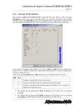
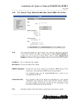
Page 80: ...connected If a system is built up of more than one frame you need the module s position in the frame as well as the number of the frame to uniquely identify a module in an Ethernet network In this ca...

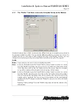
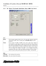
Page 81: ...able the SNMP feature If this check box is not activated no SNMP trap will be generated Individual traps can be enabled disabled by a click on the corresponding check box Thermal Control One module of...

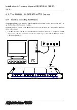
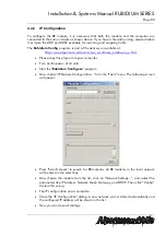
Page 82: ...server is located in the IE module and can be accessed via 10 100base T Ethernet and a web browser The IE module has a RJ45 connector for Ethernet interface Connect a straight CAT5 cable if you use a...

Page 83: ...s program to your computer Turn on the power of all units Start the Rubidium Config exe program Now choose IE Module Configuration from the Tools menu The following screen will appear Press Scan Netwo...

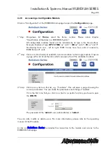
Page 84: ...or to upload them When you want to upload a file the browser has to be able to log on with the http username password example com syntax When using Microsoft Internet Explorer this feature might be d...

Page 85: ...B3 frames 21 units 2nd step Click on a blue button to establish a communication to this single module It opens a page with a list of all the links which correspond to all the available functions 3rd s...

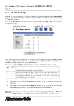
Page 86: ...e to change the set up of that specific function Click on the applicable Edit and or Use check boxes to activate deactivate a function Edit Use Function is deactivated the link is not visible Function...

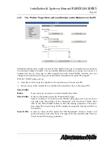
Page 87: ...dule or as a file on your PC load a set up to the module from a profile at the module or from a file at your PC Store Profile Name If you want you can enter a name to identify the profile Store Profil...

Page 88: ...nd check this new set up at your PC Click on the blue button which identifies the module Load From File A click on this button opens the Profile Upload page Click on Browse and open the file of type t...

Page 89: ...cold boot of the module Warm Boot Do a warm boot of the module SNMP Trap Enable Activate the Any Trap check box to enable the SNMP feature If this check box is not activated no SNMP trap will be gener...

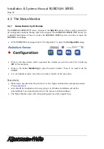
Page 90: ...ion to open the Configuration page Click on the blue button which represents the module you want to select for monitoring GT at this example Click on the button Monitoring to open the status monitor T...

Page 91: ...rmann velte com serv_e software_e software_e html Execute this program select the COM port or USB connection and press the scan button to get a list of the modules plugged to this housing Select the m...

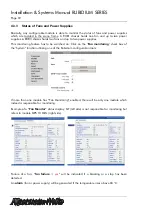
Page 92: ...as to be switched on Click on the Fan monitoring check box of the System function utilizing one of the Rubidium configuration tools If more than one module has Fan Monitoring enabled there will be onl...

Reviews: