Installation & Systems Manual RUBIDIUM SERIES
Page 17
ADR =
2
0
ADR =
1
ADR =
2
ADR =
2
1
1
PC
1
RL
C
(a
t th
e re
ar
)
till May 2011
DSUB9F
PC
since May 2011
USB 5-pin mini B
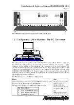
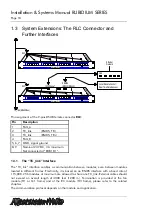
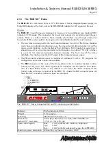
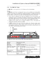
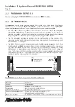
The “RUB3 H3” frame (front view): Connectors RLC and PC, slots
1.2 Configuration of the Modules: The PC Connector
AlVelte
R U B I D I U M SERIES 1
OPER
ERROR
SET
SIGNAL
OPER
ERROR
SET
SIGNAL
OPER
ERROR
SET
SIGNAL
OPER
ERROR
SET
SIGNAL
ADR = 4
ADR = 3
ADR = 2
ADR = 1
USB
RS232
PC
RLC
The slots of the frame only differ by their individual, hard wired address. Modules which can
be individually configured (e.g. the time code and video modules, but not power supply
modules), can be located by their addresses. The PC connector at the frame provides the
interface for the configuration of a module. With the aid of our configuration software each
module can be addressed and can receive a user selectable configuration. Chapter “The
RUBIDIUM CONFIGURATION PC Program” gives a short overview of the wide range of
options to set up a module. Details to the features of a single module are given in the
description of the individual module.
The PC interface can be of RS232 or USB standard:
RS232 USB
Use a straight (1:1) cable to the standard RS232 interface of a PC.
Parameter of the RS232 interface: 38400/8/E/1.
Pin assignment of the 9-pins DSUB female
PC
connector:
Pin Description
2
TxD, Transmit Data, output
3
RxD, Receive Data, input
5
GND, signal ground
Minimal requirement for
your PC: USB 1.1.
H1/S1/T1/D1/Q1:
Use a common “Type A
to Type B” cable.
H3:
USB A to 5-pin mini B
as standard accessory.

