Installation & Systems Manual RUBIDIUM SERIES
Page 70
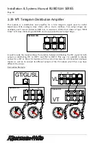
3.35
SR
: Reference Monitoring and Changeover Unit
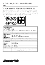
This module can compare and contrast two incoming reference signals for indescribable
differences. In the event of a failure, “SR” automatically switches to the other faultless source.
The SR module is a must for all real time reference systems where failure proof timing and
synchronisation signals are required. Additionally, it monitors the source signals for errors and
phase differences, and it makes status information about all sources available.
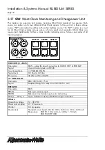
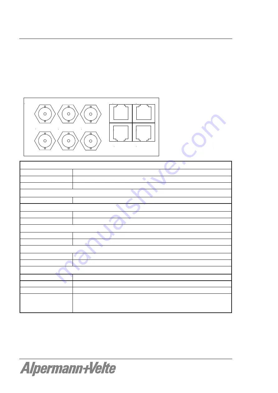
REF IN 2
GPI OUT
AlVelte
REF OUT
REF IN 1
10MHZ IN 1
10MHZ IN 2
10MHZ OUT
8 . . . . . 1
8 . . . . . 1
1 . . . . . 8
1 . . . . . 8
10 MHz IN (4 x BNC)
:
10 MHz DC range
5 V
Input impedance
2 k
Ω
Signal specifications
Frequency range: 10 MHz
5
%, amplitude range: 0.6 – 2.5 Vpp
10 MHz OUT (2 x BNC)
:
Signal
10 MHz output, switched via relay to one input
REF IN (2 x RJ45)
:
PPS IN
Pulse per second, input
RXD IN
Reference time & date input, serial data string
REF OUT (RJ45)
:
PPS OUT
Pulse per second output, switched via relay to one input
TXD OUT
Reference time & date output, switched via relay to one input
GPI OUT (RJ45)
:
FAIL Failure
signals
WARNING Warning
signals
Others
:
Operating voltage
12 - 30 V DC
Power consumption
1.5 W maximum
Weight
0.4 kg approx.
Mechanical
Standard circuit board (W x D): 100 x 160 mm / 3.94 x 6.30 inch
Rear panel: RUB H1: 103 x 44 mm / 4.06 x 1.73 inch
RUB H3: 8HP, 3RU

