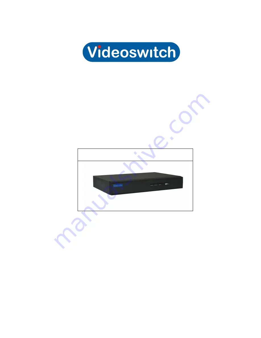
background image

Vi-P1016


HD Video Processor

Quick

Operation 

Guide

Products covered by this manual 

V

i

-

P1016

Document Reference 

Date 

BDR6

0

4a

.

pdf

1

7/0

8

/1

5

Videoswitch

 Ltd


Telephone 

01252-851510 

U

nit 15

 Redfields Industrial Park 


Fax 

01252-851296 Redfields 

Lane, Church Crookham 


Email 

[email protected] 

Hants GU52 0RD 

Web 

www.videoswitch.co.uk 

Summary of Contents for Vi-P1016

Page 1: ...red by this manual Vi P1016 Document Reference Date BDR604a pdf 17 08 15 Videoswitch Ltd Telephone 01252 851510 Unit 15 Redfields Industrial Park Fax 01252 851296 Redfields Lane Church Crookham Email sales videoswitch co uk Hants GU52 0RD Web www videoswitch co uk ...

Page 2: ...nce received including interference that may cause undesired operation EU Conformity Statement This product and if applicable the supplied accessories too are marked with CE and comply therefore with the applicable harmonized European standards listed under the Low Voltage Directive 2006 95 EC the EMC Directive 2004 108 EC the RoHS Directive 2011 65 EU 2012 19 EU WEEE directive Products marked wit...

Page 3: ...Interface are trademarks or registered trademarks of HDMI Licensing LLC The products contained in this manual are authorized by HDMI Licensing LLC with the use right of the HDMI technology VGA is the trademark of IBM UPnPTM is a certification mark of the UPnPTM Implementers Corporation Other names of companies and product contained in this manual may be trademarks or registered trademarks of their...

Page 4: ...d be installed with care Please take into consideration the following precautionary steps before installation of the Vi P1016 1 Keep all liquids away from the Vi P1016 2 Install the Vi P1016 in a well ventilated and dust free area 3 Ensure environmental conditions meet factory specifications Installation During the installation of the Vi P1016 1 Use brackets for rack mounting 2 Ensure there is amp...

Page 5: ... 1 POWER POWER indicator turns green when DVR is powered up 2 STATUS STATUS indicator lights in red when data is being read from or written to HDD 3 Tx Rx Tx Rx indictor blinks green when network connection is functioning properly 4 USB Interface Connects USB mouse or USB flash memory devices 5 IR Receiver Receiver for IR remote ...

Page 6: ...I video output 5 VGA DB15 connector for VGA output Display local video output and menu 6 AUDIO IN RCA connector for audio input 7 AUDIO OUT RCA connector for audio output 8 LAN Interface RJ45 10M 100M Ethernet interface 9 RS 485 Interface Connector for RS 485 devices Connect the D and D terminals to R and R terminals of PTZ receiver respectively 10 12V 12VDC power supply 11 POWER Switch for turnin...

Page 7: ...rm output By default jumpers are connected To connect an AC load jumpers should be removed Example If you connect an AC load to the alarm output 3 of the device then you must remove the JP3 Alarm Connection To connect alarm devices to the Vi P1016 1 Disconnect pluggable block from the ALARM IN ALARM OUT terminal block 2 Press and hold the orange part of the pluggable block insert signal cables int...

Page 8: ...0Hz 720P 1280 720 60Hz XGA 1024 768 60Hz CVBS output 1 ch BNC 1 0 Vp p 75 Ω resolution PAL 704 576 NTSC 704 480 Frame rate Real Time 25 fps External interface Network interface 1 RJ45 10M 100M Ethernet interface USB interface 2 USB 2 0 General Power supply 12 VDC Consumption without HDD or DVD R W 10 W 15 W Working temperature 10 º C 55 º C Working humidity 10 90 Chassis Standalone 1U chassis Dime...

Page 9: ...u structure varies according to different models Startup and Shutdown Proper startup and shutdown procedures are crucial to expanding the life of the Vi P1016 Before you start Check that the voltage of the extra power supply is the same with the device s requirement and the ground connection is working properly Starting up the device Steps 1 Check the power supply is plugged into an electrical out...

Page 10: ...w the guide of the Setup Wizard to configure the system resolution password modification system date time network settings etc Live View Some icons are provided on screen in Live View mode to indicate different camera status These icons include Live View Icons In the live view mode there are icons at the right top of the screen for each channel showing the status of the record and alarm in the cha...

Page 11: ...ay normal recording or motion detection recording for all channels Add IP Camera Enter the IP Camera Management interface to add the locally searched online IP camera quickly Quick Set Set the video output mode to Standard Bright Gentle or Vivid Aux Monitor Switch to the auxiliary output mode and the operation for the main output is disabled Note If you enter Aux monitor mode and the Aux monitor i...

Page 12: ...n vide output select the Main Monitor from the right click menu or use the mouse wheel to double click on the screen and then click Yes on the pop up message box Note You can select the Menu Output Mode under Menu Configuration More Settings to Auto or HDMI VGA and then restart the device to switch the main output back to HDMI VGA output Adding IP Cameras Note The connection of 1 or 2 IP cameras i...

Page 13: ...amera The camera is connected The camera is disconnected you can click the icon to get the exception information of camera Delete the IP camera Advanced settings of the camera 4 To add other IP cameras 1 Click the Custom Adding button to pop up the Add IP Camera Custom interface 2 You can edit the IP address protocol management port and other information of the IP camera to be added 3 Click Add to...

Page 14: ...ly through RS 485 interface Steps 1 Enter the PTZ Settings interface Menu Camera PTZ General 2 Choose the camera for PTZ setting in the Camera dropdown list 3 Enter the parameters of the PTZ camera Note All the parameters should be exactly the same as the PTZ camera parameters Only PTZ Protocol can be set for network cameras Example If the PTZ camera has a Baud rate as 115200 you should input 1152...

Page 15: ...ption Icon Description Direction button and the auto cycle button Zoom Focus Iris Zoom Focus Iris The speed of the PTZ movement Light on off Wiper on off 3D Zoom Image Centralization Preset Patrol Pattern Menu Previous item Next item Start pattern patrol Stop the patrol or pattern movement Minimize windows Exit Enter PTZ settings menu ...

Reviews: