Allied Vision Technologies AVT Marlin Technical Manual Download Page 235

Configuration of the camera

 MARLIN Technical Manual


V2.4.0

235

GPDATA_BUFFER

GPDATA_BUFFER is a register that regulates the exchange of data between 
camera and host for programming the LUT and the upload/download of the 
shading image.

GPDATA_INFO

Buffer size query

GPDATA_BUFFER

indicates the actual storage range

Little endian vs. big endian byte order

Read/WriteBlock accesses to GPDATA_BUFFER are recommended, to read 
or write more than 4 byte data. This increases the transfer speed com-
pared to accessing every single quadlet.

The big endian byte order of the 1394 bus is unlike the little endian 
byte order of common operating systems (Intel PC). Each quadlet of the 
local buffer, containing the LUT data or shading image for instance, has 
to be swapped bytewise from little endian byte order to big endian byte 
order before writing on the bus.
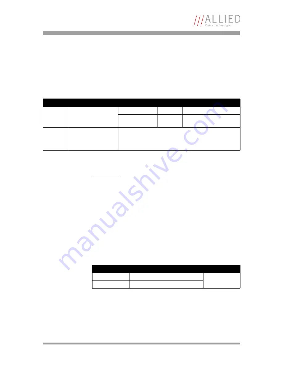
Register

Name

Field

Bit

Description

0xF1000FFC GPDATA_INFO

---

[0..15]

Reserved

BufferSize

[16..31]

Size of GPDATA_BUFFER 
(byte)

0xF1001000

0xF10017FC

GPDATA_BUFFER

 Table 131: Advanced register: 

GPData buffer

Note

L

Read the BufferSize before using.

GPDATA_BUFFER can be used by only one function at a 
time.

Bit depth

little endian

big endian

Description

8 bit

L0 L1 L2 L3

L3 L2 L1 L0

L: low byte

H: high byte

16 bit

L0 H0 L1 H1

H1 L1 H0 L0

 Table 132: Swapped first quadlet at address offset 0

Summary of Contents for AVT Marlin

Page 1: ...Technical Manual For CCD models with serial numbers xx yy 6zzzzzzz and all CMOS models V2 4 0 15 August 2008 Allied Vision Technologies GmbH Taschenweg 2a D 07646 Stadtroda Germany AVT Marlin...

Page 2: ...adio noise emissions set out in the Radio Interference Regulations Pour utilisateurs au Canada Cet appareil est conforme aux normes classe B pour bruits radio lectriques sp cifi es dans le R glement s...

Page 3: ...s 19 Camera lenses 19 Specifications 21 MARLIN F 033B C 21 MARLIN F 046B C 23 MARLIN F 080B C 30 fps 25 MARLIN F 145B2 C2 27 MARLIN F 146B C 29 MARLIN F 201B C 31 MARLIN F 131B C NIR 33 Spectral sensi...

Page 4: ...l gain 80 Brightness black level or offset 80 Look up table LUT and gamma function 82 Loading an LUT into the camera 83 Shading correction 84 How to store shading image 84 Automatic generation of corr...

Page 5: ...123 One shot command on the bus to start of exposure 123 End of exposure to first packet on the bus 124 Multi Shot 125 ISO_Enable Free Run 125 Asynchronous broadcast 125 Jitter at start of exposure 12...

Page 6: ...Configuration of the camera 171 Camera_Status_Register 171 Example 172 Sample program 173 Configuration ROM 174 Implemented registers IIDC V1 3 177 Camera initialize register 177 Inquiry register for...

Page 7: ...r control 221 Auto gain control 221 Autofunction AOI 222 Color correction 223 Trigger delay 223 Mirror image 224 Soft Reset 224 Secure image signature SIS 225 Advanced register time stamp 225 Advanced...

Page 8: ...5 2030 outside Germany USA Please check the link for your local dealer http www alliedvisiontec com partner html Ordering and commercial information customer care alliedvisiontec com phone for Germany...

Page 9: ...software on your PC or laptop FireWire card cables Version Date Remarks 0 9 18 12 2003 First issue 0 91 09 01 2004 Typos corrected minor changes spectral sensitivity of IR cut filter added 1 0 20 01...

Page 10: ...rotating in Chapter Camera dimensions on page 42 Added detailed description of BRIGHTNESS 800h in Table 94 Feature control register on page 195 Added detailed description of WHITE BALANCE 80Ch in Tab...

Page 11: ...s on page 21 Safety instructions moved to Hardware Installation Guide Chapter Safety instructions and AVT camera cleaning instructions Environmental conditions moved to Marlin Instruction Leaflet Info...

Page 12: ...238 Changed provisions directive to 2004 108 EG in Chapter Decla rations of conformity on page 18 New measurement of minimum exposure time and therefore also new offset values Table 43 Camera specific...

Page 13: ...eras Chapter Filter and lenses on page 19 describes the IR cut filter and suit able camera lenses Chapter Specifications on page 21 lists camera details and spectral sen sitivity diagrams for each cam...

Page 14: ...st Chapter How does bandwidth affect the frame rate on page 166 gives some considerations on bandwidth details Chapter Configuration of the camera on page 171 lists standard and advanced register desc...

Page 15: ...te L This symbol highlights important information Caution a This symbol highlights important instructions You have to follow these instructions to avoid malfunctions www This symbol highlights URLs fo...

Page 16: ...MARLINs having serial numbers starting with 6 after the e g Xx yy 6zzzzzzz and all CMOS versions regard less of S N For CCD MARLINs with different serial numbers the ver sion 1 2 of the Technical Manu...

Page 17: ...IEEE 1394 FireWire or i Link facilitates the simplest computer compatibility and bidirectional data transfer using the plug and play process Further development of the IEEE 1394 standard has already m...

Page 18: ...conformity with the following stan dard s or other normative document s FCC Class B CE following the provisions of 2004 108 EG directive RoHS 2002 95 EC Category Name Model Name Digital Camera IEEE 1...

Page 19: ...type distance and the focal length of the lens Figure 1 Spectral transmission of Jenofilt 217 Focal length Marlin F 033 046 145 146 Distance 0 5 m Distance 1 m 4 8 mm 0 5 m x 0 67 m 1 0 m x 1 33 m 8 m...

Page 20: ...7 m x 0 93 m 1 4 m x 1 86 m 8 mm 0 4 m x 0 53 m 0 8 m x 1 06 m 12 mm 0 27 m x 0 36 m 0 54 m x 0 72 m 16 mm 0 2 m x 0 27 m 0 4 m x 0 54 m 25 mm 12 5 cm x 16 63 cm 25 cm x 33 25 cm 35 mm 8 8 cm x 11 7...

Page 21: ...5 fps 15 fps 30 fps 60 fps Up to 73 06 fps in Format_7 Gain control Manual 0 24 dB 0 035 dB step auto gain select AOI Shutter speed 32 s 67 108 864 s 67s auto shutter select AOI External trigger shutt...

Page 22: ...re 5 C 45 C Storage temperature 10 C 60 C Regulations CE FCC Class B RoHS 2002 95 EC Standard accessories b w and color IR cut filter Optional accessories b w and color IR pass filter protection glass...

Page 23: ...transfer by command trigger delay Internal FIFO memory Up to 13 frames Number of look up tables One user programmable 10 bit 8 bit gamma 0 5 Smart functions Real time shading correction image sequenc...

Page 24: ...apter card angled head locking IEEE 1394 cable Software packages API FirePackage Direct FirePackage Fire4Linux Note L The design and specifications for the products described above may change without...

Page 25: ...s 67s auto shutter select AOI External trigger shutter Trigger_Mode_0 Trigger_Mode_1 advanced feature Trigger_Mode_15 bulk image transfer by command trigger delay Internal FIFO memory Up to 7 frames...

Page 26: ...filter IR pass filter color protection glass On request Host adapter card angled head locking IEEE 1394 cable Software packages API FirePackage Direct FirePackage Fire4Linux Note L The design and spec...

Page 27: ...gger_Mode_15 bulk image transfer by command trigger delay Internal FIFO memory Up to 3 frames Number of look up tables One user programmable 10 bit 8 bit gamma 0 5 Smart functions Real time shading co...

Page 28: ...r protection glass On request Host adapter card angled head locking IEEE 1394 cable Software packages API FirePackage Direct FirePackage Fire4Linux Note L The design and specifications for the product...

Page 29: ...transfer by command trigger delay Internal FIFO memory Up to 3 frames Number of look up tables One user programmable 10 bit 8 bit gamma 0 5 Smart functions Real time shading correction image sequenci...

Page 30: ...apter card angled head locking IEEE 1394 cable Software packages API FirePackage Direct FirePackage Fire4Linux Note L The design and specifications for the products described above may change without...

Page 31: ...igger_Mode_15 bulk image transfer by command trigger delay Internal FIFO memory Up to 2 frames Number of look up tables One user programmable 10 bit 8 bit gamma 0 5 Smart functions Real time shading c...

Page 32: ...or protection glass On request Host adapter card angled head locking IEEE 1394 cable Software packages API FirePackage Direct FirePackage Fire4Linux Note L The design and specifications for the produc...

Page 33: ...rigger_Mode_15 bulk image transfer by command trigger delay Internal FIFO memory Up to 4 frames Number of look up tables One user programmable 10 bit 8 bit separate gamma 0 5 LUT Smart functions Dark...

Page 34: ...ssories b w IR cut filter IR pass filter color protection glass On request Host adapter card angled head locking IEEE 1394 cable Software packages API FirePackage Direct FirePackage Fire4Linux Note L...

Page 35: ...ns MARLIN Technical Manual V2 4 0 35 Spectral sensitivity Figure 2 Spectral sensitivity of Marlin F 033B without cut filter and optics Figure 3 Spectral sensitivity of Marlin F 033C without cut filter...

Page 36: ...pecifications MARLIN Technical Manual V2 4 0 36 Figure 4 Spectral sensitivity of Marlin F 046B without cut filter and optics Figure 5 Spectral sensitivity of Marlin F 046C without cut filter and optic...

Page 37: ...pecifications MARLIN Technical Manual V2 4 0 37 Figure 6 Spectral sensitivity of Marlin F 080B without cut filter and optics Figure 7 Spectral sensitivity of Marlin F 080C without cut filter and optic...

Page 38: ...ecifications MARLIN Technical Manual V2 4 0 38 Figure 8 Spectral sensitivity of Marlin F 145B2 without cut filter and optics Figure 9 Spectral sensitivity of Marlin F 145C2 without cut filter and opti...

Page 39: ...ecifications MARLIN Technical Manual V2 4 0 39 Figure 10 Spectral sensitivity of Marlin F 146B without cut filter and optics Figure 11 Spectral sensitivity of Marlin F 146C without cut filter and opti...

Page 40: ...ecifications MARLIN Technical Manual V2 4 0 40 Figure 12 Spectral sensitivity of Marlin F 201B without cut filter and optics Figure 13 Spectral sensitivity of Marlin F 201C without cut filter and opti...

Page 41: ...l V2 4 0 41 Figure 14 Spectral sensitivity of Marlin F 131B with IBIS5B as standard Marlin F 131B NIR with IBIS5B NIR as standard without cut filter and optics Figure 15 Spectral sensitivity of Marlin...

Page 42: ...d housing Note L For information on sensor position accuracy sensor shift x y optical back focal length z and sensor rota tion see Chapter Sensor position accuracy of AVT cameras on page 237 Figure 16...

Page 43: ...Camera dimensions MARLIN Technical Manual V2 4 0 43 Tripod adapter Figure 17 Tripod dimensions...

Page 44: ...Camera dimensions MARLIN Technical Manual V2 4 0 44 MARLIN W90 This version has the sensor tilted by 90 degrees clockwise so that it views upwards Figure 18 MARLIN W90...

Page 45: ...sions MARLIN Technical Manual V2 4 0 45 MARLIN W90 S90 This version has the sensor tilted by 90 degrees clockwise so that it views upwards and additionally rotated by 90 degrees clockwise Figure 19 MA...

Page 46: ...s MARLIN Technical Manual V2 4 0 46 MARLIN W270 This version has the sensor tilted by 270 degrees clockwise so that it views downwards Consult your dealer if you have inquiries for this version Figure...

Page 47: ...ARLIN Technical Manual V2 4 0 47 MARLIN W270 S90 This version has the sensor tilted by 270 degrees clockwise so that it views downwards Additionally the sensor is tilted by 90 degrees clockwise Figure...

Page 48: ...ecification Note L For a detailed description of the camera interfaces FireWire I O connector ordering numbers and operat ing instructions see the Hardware Installation Guide Read all Notes and Cautio...

Page 49: ...d ext power External ground for RS232 and external power 2 External Power CCD models only 8 36 V DC Power supply 3 4 Camera In 1 In Uin high 2 V UinVCC Uin low 0 V 0 8 V Camera Input 1 GPIn1 default T...

Page 50: ...on Status LED yellow The following states are displayed via the yellow LED Figure 24 Position of Status LEDs State Description Power S2 LED off power off LED on power on Table 15 LED indication green...

Page 51: ...e of 1 5 sec Example 3 5 sec one blink 1 5 sec 2 blinks indicates a warning Format_7_Error_1 Class S1 Error code S2 Warning 1 blink DCAM 2 blinks MISC 3 blinks FPGA 4 blinks Stack 5 blinks FPGA Boot e...

Page 52: ...of the block must be present on all inputs in order to generate a trigger signal The polarity for each signal can be set separately via the inverting inputs The camera must be set to external triggeri...

Page 53: ...ription 0xF1000300 IO_INP_CTRL1 Presence_Inq 0 Indicates presence of this feature read only 1 6 Polarity 7 0 low active 1 high active 8 10 Reserved InputMode 11 15 Mode see Table 19 Input routing on p...

Page 54: ...on 0xF0F00534 TRIGGER_DELAY_INQUIRY Presence_Inq 0 Indicates presence of this feature read only Abs_Control_Inq 1 Capability of control with absolute value 2 Reserved One_Push_Inq 3 One push auto mode...

Page 55: ...0 Presence of this feature 0 N A 1 Available Abs_Control 1 Absolute value control O Control with value in the value field 1 Control with value in the absolute value CSR If this bit 1 the value in the...

Page 56: ...s and warnings see the Hardware Installation Guide Chapter MARLIN output description Signal Description IntEna Integration Enable signal This signal displays the time in which exposure was made By usi...

Page 57: ...ARLIN Technical Manual V2 4 0 57 Figure 26 Output block diagram IntEna Output signal Opto Coupler Polarity selectable via software Operation state read FVal Busy Operation state read Output mode selec...

Page 58: ...ardless of the output mode This allows for example the host com puter to determine if the camera is busy by simply polling the BUSY output Note L Outputs in Direct Mode For correct functionality the P...

Page 59: ...am illustrates the dependencies of the various output sig nals ID Mode Default 0x00 Off 0x01 Output state follows PinState bit Using this mode the Polarity bit has to be set to 0 not inverted This is...

Page 60: ...IN Technical Manual V2 4 0 60 Figure 27 Output Impulse Diagram Note L The signals can be inverted Caution a Firing a new trigger while IntEna is still active can result in image corruption due to doub...

Page 61: ...eas the IntEna_Delay only delays the leading edge of the IntEna output signal but does not delay the image capture As mentioned before it is possible to set the outputs by software Doing so the achiev...

Page 62: ...ber of bytes in the data field tg Tag field shall be set to zero channel Isochronous channel number as programmed in the iso_channel field of the cam_sta_ctrl register tCode Transaction code shall be...

Page 63: ...Camera interfaces MARLIN Technical Manual V2 4 0 63 Figure 30 Y8 and Y16 format Source IIDC V1 3...

Page 64: ...Camera interfaces MARLIN Technical Manual V2 4 0 64 Figure 31 Data structure Source IIDC V1 3...

Page 65: ...following para graphs For sensor data see Chapter Specifications on page 21 Black and white cameras Figure 32 Block diagram b w camera Analog Gain Analog Offset CCD 12 bit Shading Correction 10 bit L...

Page 66: ...DC 10 bit CCD Integrated in Analog Front End AFE 8 Bit Test Pattern Auto Data 10 Bit 8 Bit Frame Memory 8 10 Bit Graphics Overlay 10 Bit Horizontal Mirror 10 Bit Horizontal Masking Sharpness Camera Co...

Page 67: ...s represent the analogue signal on the photo diode which decreases as a result of exposure The slope is determined by the amount of light at each pixel the more light the steeper the slope When the pi...

Page 68: ...d green P1 and green P2 MARLIN F 131 with three knee points The MARLIN F 131 offers up to three knee points when in global shutter mode This functionality is controlled via the following registers Reg...

Page 69: ...needs to be written For further tuning readjust KNEEPOINT_X but maintain ratio KNEEPOINT_1 KNEEPOINT_2 KNEEPOINT_3 The figure below taken from the sensor s data sheet illustrates the nonlinear behavi...

Page 70: ...r output by 9 5 dB in 106 steps relative to the channel with highest output The following screenshot is taken from the data sheet of the AFE and illus trates the details The analog color signal coming...

Page 71: ...field will be ignored 2 4 Reserved One_Push 5 Write 1 begin to work self cleared after operation Read 1 in operation 0 not in operation If A_M_Mode 1 this bit will be ignored ON_OFF 6 Write ON or OFF...

Page 72: ...qual i e it assumes that the average of the sampled grid pix els is to be monochrome If the image capture is active e g IsoEnable set in register 614h the frames used by the camera for white balance a...

Page 73: ...age For the white balance algorithm a grid is used of at least 300 samples equally spread over the area of interest or a fraction of it AUTOFNC_AOI affects the auto shutter auto gain and auto white ba...

Page 74: ...B component sums of the samples shall be equal i e it assumes that the mean of the sampled grid pixels is to be monochrome Note L If the adjustment fails and the work area size and or position become...

Page 75: ...hutter limits or within those set in advanced register F1000360h in order to reach the reference brightness set in auto exposure register Increasing the auto exposure value increases the average brigh...

Page 76: ...4 Reserved One_Push 5 Write 1 begin to work self cleared after oper ation Read 1 in operation 0 not in operation If A_M_Mode 1 this bit will be ignored ON_OFF 6 Write ON or OFF this feature Read read...

Page 77: ...es This is done to achieve the best image quality with lowest noise For increasing brightness priority is given to lowering gain first for the same purpose Note L Values can only be changed within the...

Page 78: ...to achieve minimum delay with zero overshot The following table shows both the gain and auto exposure CSR Register Name Field Bit Description 0xF0F00820 GAIN Presence_Inq 0 Presence of this feature 0...

Page 79: ...served One_Push 5 Write Set bit high to star Read Status of the feature Bit high WIP Bit low Ready ON_OFF 6 Write ON or OFF this feature Read read a status 0 OFF 1 ON A_M_MODE 7 Write set mode Read re...

Page 80: ...odel 0 127 8 bit The formula for gain and offset setting is Y G x Y Offset Note L Values can only be changed within the limits of gain CSR Changes in auto exposure register only have an effect when au...

Page 81: ...e of this feature 0 N A 1 Available Abs_Control 1 Absolute value control O Control with value in the value field 1 Control with value in the absolute value CSR If this bit 1 the value in the value fie...

Page 82: ...he values of functions which are calculated offline e g with a spreadsheet program This function needs to be loaded into the camera s RAM before use One example of using a LUT is the gamma LUT Output...

Page 83: ...CCD models is also imple mented via the look up table it is not possible to use a different LUT when gamma correction is enabled With all CCD models the user LUT will be overwritten when Gamma is enab...

Page 84: ...generating the shading image in the camera it can be uploaded to the host computer for nonvolatile storage purposes The following pictures describe the process of automatic generation of cor rection d...

Page 85: ...t in the GRAB_COUNT register Recommended values are 4 8 or 16 An arithmetic mean value is calculated from them to reduce noise After this a search is made for the brightest pixel in the mean value fra...

Page 86: ...ottom picture shows the shading corrected output image unfocused lens Note L Configuration To configure this feature in an advanced register See Table 108 Advanced register Shading on page 214 Note L...

Page 87: ...Description of the data path MARLIN Technical Manual V2 4 0 87 Figure 44 Generation of shading image...

Page 88: ...he largest displayable frame format This ensures that any smaller AOIs are completely cov ered by the shading correction The automatic generation of shading data can also be enabled when image capture...

Page 89: ...ware 3 03 it is possible to read quadlets directly out of the buffer but this takes much more time Figure 46 Uploading shading image to host Note L Configuration To configure this feature in an advan...

Page 90: ...3 03 it is possible to write quadlets directly into the buffer but this takes much more time Figure 47 Loading the shading reference image Note L Configuration To configure this feature in an advanced...

Page 91: ...left picture without correction it can be seen that over the complete field of view there is a certain spread of the histogram indicating non uni form dark pixels and blemished pixel s with brightnes...

Page 92: ...ged Generate the image by closing the lens to eliminate image information DSNU correction feature is not available for the Marlin F 131C The FPN correction in former releases of the Marlin F 131 worke...

Page 93: ...is function is especially useful when the camera is looking at objects with the help of a mirror or in certain microscopy applications Note L Configuration To configure this feature in an advanced reg...

Page 94: ...in regard to the maximum wanted signal intensity expected The higher this value the better the signal quality The unit of measurement used is generally known as the decibel dB a logarithmic power lev...

Page 95: ...ion by about 2 dB Format_7 Mode_2 By default use Format_7 Mode_2 for 2 x vertical binning This reduces vertical resolution depending on the model Figure 51 2 x vertical binning Note L Vertical resolut...

Page 96: ...factor of two 6 dB Signal to noise separation improves by approx 3 dB Horizontal resolution is lowered depending on the model Horizontal resolution Horizontal resolution is lowered depending on the m...

Page 97: ...are put together and then combined vertically Light sensitivity This increases light sensitivity by a total of a factor of 4 and at the same time signal to noise separation is improved by about 6 dB R...

Page 98: ...ion in the number of pixels and thus the amount of data while retaining the original image area angle and image brightness CMOS an increase in the frame rate Similar to binning mode the cameras suppor...

Page 99: ...Manual V2 4 0 99 Figure 54 Horizontal sub sampling 1 out of 2 b w Figure 55 Horizontal sub sampling 2 out of 4 color Note L The image appears horizontally compressed in this mode and no longer exhibi...

Page 100: ...N Technical Manual V2 4 0 100 Format_7 Mode_2 Only MF 131B C By default use Format_7 Mode_2 for b w cameras 1 out of 2 vertical sub sampling color cameras 2 out of 4 vertical sub sampling Figure 56 Ve...

Page 101: ...131B 1 out of 2 H V sub sampling only Marlin F 131C 146C 201C 2 out of 4 H V sub sampling Figure 57 Vertical sub sampling color Note L The image appears vertically compressed in this mode and does no...

Page 102: ...l Manual V2 4 0 102 Figure 59 2 out of 4 H V sub sampling color Note L Changing sub sampling modes involve the generation of new shading reference images due to a change in the image size 2 out of 4 H...

Page 103: ...nge command becomes effective with the next falling edge of sync and finally the image taken with shutter 200 is output with a considerable delay Parameters that are sent to the camera faster than the...

Page 104: ...els in a BAYER mosaic layout An effective Bayer RGB color interpolation already takes place in all Marlin color version cameras Before converting to the YUV format color correction is done after BAYER...

Page 105: ...e L If the PC does not perform BAYER to RGB post processing the b w image will be superimposed with a checkerboard pattern Figure 62 Bayer demosaicing interpolation Note L On the color camera a wrongl...

Page 106: ...btracts out this overlap Color correction in AVT cameras In AVT cameras the color correction is realized as an additional step in the process from the sensor data to color output Color correction is u...

Page 107: ...etting of zero changes the image to black and white and a set ting of 511 doubles the color intensity compared to the nominal one at 256 Note L Configuration To configure this feature in an advanced r...

Page 108: ...94 address range will be sent through the serial interface Incoming data of the serial interface is put in a camera buffer and can be polled via simple read commands from this buffer Controlling regis...

Page 109: ...s reserved Char_Length 8 15 Character length setting WR Set data length 7 or 8 bit RD Get data length 7 7 bit 8 8 bit Other values reserved Parity 16 17 Parity setting WR Set parity RD Get parity sett...

Page 110: ...1 ready 9 Reserved RDRD 10 Receive data buffer ready Read only 0 not ready 1 ready 11 Reserved ORER 12 Receive data buffer overrun error Read current status WR 0 no error to clear status 1 Ignored FER...

Page 111: ...ntrol RD Number of bytes written to transmit FIFO WR Number of bytes to transmit 16 31 Reserved 010h 0FFh Reserved 100h SIO_DATA_REGISTER CHAR_0 0 7 Character_0 RD Read character from receive buffer W...

Page 112: ...rite data 1 Query TDRD flag buffer ready and write the number of bytes to send copied from SIO register to transmit FIFO to TBUF_CNT 2 Read the available data space left in TBUF_ST if the buffer can h...

Page 113: ...ten the exposure or integration time The curtain s width defines the integration time and the curtain sweeps with the frame readout time over the image Although this is appropriate for still images im...

Page 114: ...63 Trigger_mode_0 and 1 Shutter register value External Trigger input after inverting opto coupler Integration Time External Trigger input after inv Opto External Trigger input as applied at input pin...

Page 115: ...vent can be used to trigger a multitude of internal image intakes This is especially useful for Grabbing exactly one image based on the first external trigger Filling the camera s internal image buffe...

Page 116: ...or OFF this feature Read read a status 0 OFF 1 ON If this bit 0 other fields will be read only Trigger_Polarity 7 Select trigger polarity Except for software trigger If Polarity_Inq is 1 Write to chan...

Page 117: ...precisely with the first external trigger To repeat rewrite line three Line 3 toggles one shot bit 0 of the one shot register 61C so that only one image is grabbed based on the first external trig ger...

Page 118: ...ame Field Bit Description 0xF0F00534 TRIGGER_DLY_INQUIRY Presence_Inq 0 Indicates presence of this feature read only Abs_Control_Inq 1 Capability of control with absolute value 2 Reserved One_Push_Inq...

Page 119: ...bsolute value CSR If this bit 1 the value in the Value field has to be ignored 2 5 Reserved ON_OFF 6 Write ON or OFF this feature Read read a status 0 OFF 1 ON If this bit 0 other fields will be read...

Page 120: ...r is in the range between 1 and 4095 The shutter register value is multiplied by the time base register value see Table 103 Timebase ID on page 209 The default value here is set to 20 s A camera speci...

Page 121: ...39 s Marlin F 131 1 s Table 43 Camera specific minimum exposure time Camera model Minimum exposure time Effective min exp time Min exp time offset Marlin F 033 20 s 20 s 12 s 32 s Marlin F 046 20 s 2...

Page 122: ...ter Name Field Bit Description 0xF100020C EXTD_SHUTTER Presence_Inq 0 Indicates presence of this feature read only 1 5 Reserved ExpTime 6 31 Exposure time in s Table 46 Advanced register extended shut...

Page 123: ...era to grab exactly one image with an external trigger edge If there is no trigger impulse after the camera has been armed one shot can be cancelled by clearing the bit One shot command on the bus to...

Page 124: ...o the FRAME_BUFFER before being transmitted to the bus The time from the end of exposure to the start of transport on the bus is 500 s 62 5 s This time jitters with the cycle time of the bus 125 s Fig...

Page 125: ...images based on an external trigger This is especially helpful in combination with the so called Deferred_Mode to limit the num ber of grabbed images to the FIFO size ISO_Enable Free Run Setting the...

Page 126: ...exposure starts Owing to the well known fact that an Interline Transfer CCD sensor has both a light sensitive area and a separate storage area it is common to interleave image exposure of a new frame...

Page 127: ...al is inactive the sensor is ready the camera is idle In this case the camera can resynchronize the horizontal clock to the new trigger event leaving only a very short uncertainty time of the master c...

Page 128: ...operates according to the FIFO first in first out principle This makes addressing for individual images unnecessary Deferred image transport is especially useful for multi camera applications Assumin...

Page 129: ...camera The camera sends the number of images that are entered in the NumOfImages parameter If NumOfImages is 0 all images stored in FIFO are sent If NumOfImages is not 0 the corresponding number of i...

Page 130: ...er register even while the camera is running An uncertainty of one or two images remains because normally the host does not know especially with external trigger when the next image will arrive Sequen...

Page 131: ...ithin a sequence Note L Sequence mode requires not only FW 3 03 but also special care if changing image size Color_Coding_ID and frame rate related parameters This is because these changes not only af...

Page 132: ...4 Reserved ApplyParameters 5 Apply settings to selected image of sequence auto reset IncImageNo 6 Increment ImageNo after ApplyParameters has finished 7 23 Reserved ImageNo 24 31 Number of image withi...

Page 133: ...om the corresponding FIFOs e g information for exposure time Figure 70 Sequence mode flow diagram Set SEQUENCE_CTRL ON_OFF flag to true 1 Set SeqLength to desired length MaxLength Set ImageNo 0 in SEQ...

Page 134: ...led the camera can use the FIFO for other tasks For this reason a sequence must be loaded back into the camera after sequence mode has been cancelled To repeat the sequence stop the camera and send th...

Page 135: ...only the value of a specific register and all other registers should not be changed the ApplyParameters flag may not be used here The values stored for individual images can no longer be read If the c...

Page 136: ...amera runs in continuous mode the check of monotonically changing bus cycle time is a simple test that no image was skipped or lost in the camera or subsequently in the image processing chain In synch...

Page 137: ...rame rates can only be achieved with shutter settings lower than 1 framerate This means that with default shutter time of 40 ms a camera will not achieve frame rates higher than 25 frames s In order t...

Page 138: ...Mono8 x x x x x x x x x x 6 640 x 480 Mono16 x x x x Table 52 Video fixed formats Marlin F 033B F 033C Format Mode Resolution Color mode Maximal S400 frame rates for Format_7 modes 7 0 656 x 494 656 x...

Page 139: ...x x x x x x x x x x 6 640 x 480 Mono16 x x x x Table 54 Video formats Marlin F 046B F 046C Format Mode Resolution Color mode Maximal S400 frame rates for Format_7 modes 7 0 780 x 582 780 x 580 Mono8 M...

Page 140: ...x x x 4 1024 x 768 RGB8 x x 5 1024 x 768 Mono8 x x x x x x x 6 800 x 600 Mono16 x x x x 7 1024 x 768 Mono16 x x x Table 56 Video fixed formats Marlin F 080B F 080C 30 fps Format Mode Resolution Color...

Page 141: ...480 YUV422 x x x 4 640 x 480 RGB8 x x x 5 640 x 480 Mono8 x x x x x x 6 640 x 480 Mono16 x x x 1 0 800 x 600 YUV422 x x x 1 800 x 600 RGB8 x x 2 800 x 600 Mono8 x x x x 3 1024 x 768 YUV422 x x 4 1024...

Page 142: ...92 x 1040 1392 x 1038 Mono8 Mono16 YUV411 YUV422 RGB8 RAW8 10 fps 10 fps 10 fps 10 fps 7 5 fps 10 fps 1 696 x 1040 1392 x 1040 Mono8 Mono16 Mono8 RAW 10 fps H binning 10 fps H binning 10 fps Raw Bayer...

Page 143: ...UV422 x x x x 4 640 x 480 RGB8 x x x x 5 640 x 480 Mono8 x x x x x x x 6 640 x 480 Mono16 x x x x 1 0 800 x 600 YUV422 x x x 1 800 x 600 RGB8 x x 2 800 x 600 Mono8 x x x x 3 1024 x 768 YUV422 x x x 4...

Page 144: ...mal S400 frame rates for Format_7 modes 7 0 1392 x 1040 1392 x 1038 Mono8 Mono16 YUV411 YUV422 RGB8 RAW8 17 43 fps 11 32 fps 15 1 fps 11 3 fps 7 55 fps 17 47 fps 1 696 x 1040 1392 x 1040 Mono8 Mono16...

Page 145: ...x x 4 640 x 480 RGB8 x x x 5 640 x 480 Mono8 x x x x x x 6 640 x 480 Mono16 x x x 1 0 800 x 600 YUV422 x x x 1 800 x 600 RGB8 x x 2 800 x 600 Mono8 x x x x 3 1024 x 768 YUV422 x x x 4 1024 x 768 RGB8...

Page 146: ...43 fps 12 52 fps 1 812 x 1236 1628 x 1236 Mono8 Mono16 Mono8 RAW 12 48 fps H binning 12 48 fps H binning 12 48 fps 2 1628 x 618 812 x 616 Mono8 Mono16 YUV411 YUV422 RGB8 RAW8 22 35 fps V binning 16 2...

Page 147: ...2 x x x 4 640 x 480 RGB 5 640 x 480 Mono8 x x x x 6 640 x 480 Mono16 1 0 800 x 600 YUV422 x x x 1 800 x 600 RGB 2 800 x 600 Mono8 x x x x 3 1024 x 768 YUV422 x x x 4 1024 x 768 RGB 5 1024 x 768 Mono8...

Page 148: ...rates for Format_7 modes 7 0 1280 x 1024 1280 x 1020 Mono8 YUV411 YUV422 25 fps 17 fps 12 fps 1 640 x 1024 640 x 1020 Mono8 YUV411 YUV422 48 fps H sub sampling 33 fps 25 fps 2 1280 x 512 1280 x 508 Mo...

Page 149: ...is fixed by the IIDC specification thereby determining the highest possible frame rate in Format_7 mode the user can set the upper left corner and width and height of the section area of interest AOI...

Page 150: ...e for reading the image from the sensor and transporting it into the FRAME_BUFFER The time for transferring the image over the FireWire bus The length of the exposure time Figure 72 Area of Interest A...

Page 151: ...least 300 sample points equally spread over the AOI Figure 73 Example of autofunction AOI Show work area is on Note L Autofunction AOI is independent from Format_7 AOI settings If you switch off autof...

Page 152: ...r the frame rate there is more data to be transmitted The following tables indicate the volume of data in various formats and modes to be sent within one cycle 125 s at 400 Mbit s of bandwidth The tab...

Page 153: ...on 60 fps 30 fps 15 fps 7 5 fps 3 75 fps 0 0 160 x 120 YUV444 24 bit pixel 1 2H 80p 60q 1 4H 40p 30q 1 8H 20p 15q 1 320 x 240 YUV422 16 bit pixel 1H 320p 160q 1 2H 160p 80q 1 4H 80p 40q 1 8H 40p 20q 2...

Page 154: ...1000q 5 2H 2000p 500q 5 4H 1000p 250q 5 8H 500p 125q 3 1024 x 768 YUV422 16 bit pixel 3 2H 1536p 768q 3 4H 768p 384q 3 8H 384p 192q 3 16H 192p 96q 4 1024 x 768 RGB 24 bit pixel 3 4H 768p 576q 3 8H 384...

Page 155: ...pixel 1H 1280p 960q 1 2H 640p 480q 1 4H 320p 240q 2 1280 x 960 Y Mono8 8 bit pixel 2H 2560p 640q 1H 1280p 320q 1 2H 640p 160q 1 4H 320p 80q 3 1600 x 1200 YUV422 16 bit pixel 5 4H 2000p 1000q 5 8H 1000...

Page 156: ...ext chapters Max frame rate of CCD theoretical formula Diagram of frame rates as function of AOI by constant width Table with max frame rates as function of AOI by constant width Note L Different valu...

Page 157: ...ate fps Tframe ms 494 74 15 13 49 480 76 02 13 15 400 88 79 11 26 320 106 71 9 37 240 133 71 7 48 120 215 48 4 64 20 439 41 2 28 Table 70 Frame rates MARLIN F 033 as function of AOI height frame rate...

Page 158: ...ps Tframe ms 582 53 02 18 86 480 62 51 16 00 400 72 70 13 75 320 86 88 11 51 300 91 33 10 95 240 107 92 9 27 120 169 48 5 90 20 323 07 3 10 Table 71 Frame rates MARLIN F 046 as function of AOI height...

Page 159: ...frame ms 778 20 16 49 60 770 20 34 49 16 768 20 39 49 04 760 20 57 48 60 500 29 21 34 24 490 29 68 33 69 480 30 18 33 14 Table 72 Frame rates MARLIN F 080 as function of AOI height frame rate 1 TCh eT...

Page 160: ...470 30 69 32 58 460 31 22 32 03 450 31 77 31 48 240 50 31 19 88 120 75 48 13 25 110 78 76 12 70 100 82 34 12 14 90 86 27 11 59 80 90 58 11 04 70 95 35 10 49 60 100 66 9 93 AOI height Frame rate fps T...

Page 161: ...ates of MARLIN F 080 30 fps as function of AOI height AOI height Frame rate fps Tframe ms 778 30 24 33 06 768 30 58 32 70 600 37 72 26 51 480 45 26 22 09 240 75 44 13 26 120 113 16 8 84 60 150 88 6 63...

Page 162: ...78 Frame rates MARLIN F 145 as function of AOI height AOI height Frame rate fps Tframe ms 1040 10 38 96 39 960 11 04 90 57 600 15 53 64 40 480 17 96 55 67 240 26 16 38 23 120 33 90 29 50 60 39 78 25...

Page 163: ...s MARLIN F 146 as function of AOI height AOI height Frame rate fps Tframe ms 1040 17 47 57 23 1024 17 69 56 54 960 18 59 53 79 768 21 96 45 53 600 26 10 38 31 480 30 16 33 16 240 43 78 22 84 120 56 55...

Page 164: ...on of AOI height AOI height Frame rate fps Tframe ms 1236 12 51 79 94 1200 12 84 77 89 1100 13 86 72 17 1040 14 55 68 75 1024 14 74 67 83 960 15 58 64 18 768 18 79 53 22 600 22 92 43 62 480 27 20 36 7...

Page 165: ...view in both vertical as well as horizontal direction gives a proportional increase in speed This is in contrary to CCD sensors where the horizontal image limit does not increase the frame rate In or...

Page 166: ...relationship between the required Byte_Per_Packet size and certain variables for the image It is valid only for Format_7 If the value for BYTE_PER_PACKET is greater than 4096 the maximum data payload...

Page 167: ...RLIN Technical Manual V2 4 0 167 Example formula for the b w camera Mono16 1392 x 1040 15 fps desired Formula 14 Example max frame rate calculation BYTE_PER_PACKET 15 1392 1040 2 125 s 5428 4096 frame...

Page 168: ...1 is static Image 2 moves upwards by 1 pixel frame FirePackage Fire4Linux 1 Start SmartView 2 Click the Edit settings button 3 Click Adv1 tab 4 In combo box Test images choose Image 1 or another test...

Page 169: ...ame rate MARLIN Technical Manual V2 4 0 169 Test images for color cameras The color cameras have the following test images YUV422 mode Formula 15 Calculating the gray value Figure 82 Color test image...

Page 170: ...4 0 170 Mono8 raw data The color camera outputs Bayer coded raw data in Mono8 instead of as described in IIDC V1 3 a real Y signal Figure 83 Bayer coded test image Note L The first pixel of the image...

Page 171: ...by IIDC formerly DCAM Digital Camera Specification published by the IEEE 1394 Trade Association IIDC is primarily concerned with setting memory addresses e g CSR Camera_Status_Register and their meani...

Page 172: ...MSB Most Significant Bit LSB Least Significant Bit Example This requires for example that to enable ISO_Enabled mode see Chapter ISO_Enable Free Run on page 125 bit 0 in register 614h the value 80000...

Page 173: ...he FireCtrl DLL from the FirePackage API Also shown is how the camera is switched into ISO_Enabled mode WriteQuad m_cmdRegBase CCR_FRAME RATE Frame Rate 29 WriteQuad m_cmdRegBase CCR_VMODE mode 29 Wri...

Page 174: ...cific base address The entry with key 8D in the root directory 420h in this case provides the offset for the Node unique ID leaf To compute the effective start address of the node unique ID leaf Note...

Page 175: ...ute the effective start address of the node unique ID leaf currAddr node unique ID leaf address destAddr address of directory entry addrOffset value of directory entry destAddr currAddr 4 x addrOffset...

Page 176: ...ress of the camera control register is thus FFFF F0F00000h The offset entered in the table always refers to the base address of F0F00000h Offset 0 7 8 15 16 23 24 31 444h 00 03 7F 89 Unit dependent in...

Page 177: ...und in the Description column Camera initialize register Inquiry register for video format Offset Name Description 000h INITIALIZE Assert MSB 1 for Init Table 86 Camera initialize register Offset Name...

Page 178: ...600 YUV422 Mode _1 1 800 x 600 RGB Mode _2 2 800 x 600 Mono8 Mode _3 3 1024 x 768 YUV422 Mode _4 4 1024 x 768 RGB Mode _5 5 1024 x 768 Mono8 Mode _6 6 800 x 600 Mono16 Mode _7 7 1024 x 768 Mono16 8 3...

Page 179: ...ATE_INQ Format_0 Mode_0 FrameRate_0 0 Reserved FrameRate _1 1 Reserved FrameRate _2 2 7 5 fps FrameRate _3 3 15 fps FrameRate _4 4 30 fps FrameRate _5 5 60 fps FrameRate _6 6 120 fps IIDC V1 31 FrameR...

Page 180: ...FrameRate_0 0 1 875 fps FrameRate _1 1 3 75 fps FrameRate _2 2 7 5 fps FrameRate _3 3 15 fps FrameRate _4 4 30 fps FrameRate _5 5 60 fps FrameRate _6 6 120 fps IIDC V1 31 FrameRate _7 7 240 fps IIDC V...

Page 181: ...1 1 3 75 fps FrameRate _2 2 7 5 fps FrameRate _3 3 15 fps FrameRate _4 4 30 fps FrameRate _5 5 60 fps FrameRate _6 6 120 fps IIDC V1 31 FrameRate _7 7 240 fps IIDC V1 31 8 31 Reserved zero 21Ch 21Fh R...

Page 182: ...FrameRate_0 0 Reserved FrameRate _1 1 Reserved FrameRate _2 2 7 5 fps FrameRate _3 3 15 fps FrameRate _4 4 30 fps FrameRate _5 5 60 fps FrameRate _6 6 120 fps IIDC V1 31 FrameRate _7 7 240 fps IIDC V1...

Page 183: ...FrameRate_0 0 1 875 fps FrameRate _1 1 3 75 fps FrameRate _2 2 7 5 fps FrameRate _3 3 15 fps FrameRate _4 4 30 fps FrameRate _5 5 60 fps FrameRate _6 6 120 fps IIDC V1 31 FrameRate _7 7 240 fps IIDC V...

Page 184: ...ormat_2 Mode_0 FrameRate_0 0 1 875 fps FrameRate _1 1 3 75 fps FrameRate _2 2 7 5 fps FrameRate _3 3 15 fps FrameRate _4 4 30 fps FrameRate _5 5 60 fps FrameRate _6 6 Reserved FrameRate _7 7 Reserved...

Page 185: ...rmat_2 Mode_3 FrameRate_0 0 1 875 fps FrameRate _1 1 3 75 fps FrameRate _2 2 7 5 fps FrameRate _3 3 15 fps FrameRate _4 4 30 fps FrameRate _5 5 60 fps FrameRate _6 6 Reserved FrameRate _7 7 Reserved 8...

Page 186: ...meRate _3 3 15 fps FrameRate _4 4 30 fps FrameRate _5 5 60 fps FrameRate _6 6 Reserved FrameRate _7 7 Reserved 8 31 Reserved zero 25Ch V_RATE_INQ Format_2 Mode_7 FrameRate_0 0 1 875 fps FrameRate _1 1...

Page 187: ...adlet offset for Format_7 Mode_2 2ECh V CSR_INQ_7_3 0 31 CSR_quadlet offset for Format_7 Mode_3 2F0h V CSR_INQ_7_4 0 31 CSR_quadlet offset for Format_7 Mode_4 2F4h V CSR_INQ_7_5 0 31 CSR_quadlet offse...

Page 188: ...rol_Error_Status_Inq 2 Inquiry for existence of Feature_Control_Error_Status Opt_Func_CSR_Inq 3 Inquiry for Opt_Func_CSR 4 7 Reserved 1394b_mode_Capability 8 Inquiry for 1394b_mode_Capability 9 15 Res...

Page 189: ...Focus 10 Focus control Temperature 11 Temperature control Trigger 12 Trigger control Trigger_Delay 13 Trigger delay control White_Shading 14 White shading control Frame_Rate 15 Frame rate control 16 3...

Page 190: ...should still always be activated first Advanced Feature Set Unique Value is 7ACh and CompanyID is A47h 484h PIO_Control_CSR_Inq PIO_Control_Quadlet_Offset 0 31 Quadlet offset of the PIO_Control CSR s...

Page 191: ...ntrolled auto matically by the camera Manual_Inq 7 Manual Mode controlled by user Min_Value 8 19 Min value for this feature Max_Value 20 31 Max value for this feature 504h AUTO_EXPOSURE_INQ Same defin...

Page 192: ...er_Mode 2 Trigger_Mode3_Inq 19 Presence of Trigger_Mode 3 20 31 Reserved 534h TRIGGER_DELAY_INQUIRY Presence_Inq 0 Indicates presence of this feature read only Abs_Control_Inq 1 Capability of control...

Page 193: ...DE Bits 0 2 for the current video mode 608h CUR V FORMAT Bits 0 2 for the current video format 60Ch ISO Channel Bits 0 3 for channel 6 7 for ISO speed 610h Camera_Power Always 0 614h ISO_EN Continuous...

Page 194: ...ABS_CSR_HI_INQ_6 Always 0 71Ch ABS_CSR_HI_INQ_7 Always 0 720h ABS_CSR_HI_INQ_8 Always 0 724h ABS_CSR_HI_INQ_9 Always 0 728h ABS_CSR_HI_INQ_10 Always 0 72Ch ABS_CSR_HI_INQ_11 Always 0 730h ABS_CSR_HI_I...

Page 195: ...ntrol with value in the Value field 1 Control with value in the Absolute value CSR If this bit 1 value in the Value field is ignored 2 4 Reserved One_Push 5 Write 1 begin to work Self cleared after op...

Page 196: ...al Manual V2 4 0 196 804h AUTO EXPOSURE See above Note Target grey level parameter in SmartView corresponds to Auto_exposure register 0xF0F00804 IIDC 808h SHARPNESS See above Offset Name Field Bit Des...

Page 197: ...ration Value 0 not in operation If A_M_Mode 1 this bit is ignored ON_OFF 6 Write ON or OFF this feature Read read a status 0 OFF 1 ON If this bit 0 other fields will be read only A_M_Mode 7 Write set...

Page 198: ...Always 0 82Ch TEMPERATURE Always 0 830h TRIGGER MODE Can be effected via Advanced Feature IO_INP_CTRLx 834h 87C Reserved for other FEATURE_HI Always 0 880h Zoom Always 0 884h PAN Always 0 888h TILT Al...

Page 199: ...89 Frame rate inquiry register on page 179 gives 003C2400h 4 x 003C2400h F09000h so that the base address for the latter Table 96 Format_7 control and status register on page 199 equals to F0000000h...

Page 200: ...elevant to Format_7 are refreshed on each access The Setting_1 bit is automatically cleared after each access When ErrorFlag_1 or ErrorFlag_2 are set and Format_7 is configured no image capture is sta...

Page 201: ...able 98 Advanced register Version information on page 204 0XF1000040 ADV_INQ_1 See Table 100 Advanced register Advanced fea ture inquiry on page 206 0XF1000044 ADV_INQ_2 0XF1000200 MAX_RESOLUTION See...

Page 202: ...control on page 53 0XF1000304 IO_INP_CTRL2 0XF1000308 IO_INP_CTRL3 Dolphin series only 0XF1000320 IO_OUTP_CTRL1 See Table 24 Advanced register Output control on page 58 0XF1000324 IO_OUTP_CTRL2 0XF100...

Page 203: ...Advanced register Time stamp on page 226 0XF1000610 FRMCNT_STAMP See Table 126 Advanced register Frame counter on page 228 0XF1000620 TRGCNT_STAMP See Table 127 Advanced register Trigger counter on pa...

Page 204: ...The FPGA type ID camera type ID identifies the camera type with the help of the following list Register Name Field Bit Description F1000010 VERSION_INFO1 C type ID 0 15 Reserved C version 16 31 Bcd co...

Page 205: ...6B 24 M2F046C 25 M2F080B 26 M2F080C 27 M2F145B2 28 M2F145C2 31 M2F145B2 15fps 32 M2F145C2 15fps 38 OF320C 40 OF510C 42 OF810C 43 M2F080B 30fps 44 M2F080C 30fps 45 M2F145B2 ASM 46 MM2F145C2 ASM 47 M2F2...

Page 206: ...or not Register Name Field Bit Description 0xF1000040 ADV_INQ_1 MaxResolution 0 TimeBase 1 ExtdShutter 2 TestImage 3 FrameInfo 4 Sequences 5 VersionInfo 6 7 Reserved Look up tables 8 Shading 9 Deferre...

Page 207: ...served 18 31 Reserved 0xF1000048 ADV_INQ_3 0 31 Reserved 0xF100004C ADV_INQ_4 0 31 Reserved Note L This register normally outputs the MAX_IMAGE_SIZE_INQ Format_7 Mode_0 value This is the value given i...

Page 208: ...s increments with the shutter control The ExpOffset field specifies the camera specific exposure time offset in microseconds s This time which should be equivalent to Table 43 Cam era specific minimum...

Page 209: ...mera MARLIN Technical Manual V2 4 0 209 ID Timebase s 0 1 1 2 2 5 3 10 4 20 Default value 5 50 6 100 7 200 8 500 9 1000 Table 103 Timebase ID Note L The ABSOLUTE VALUE CSR register introduced in IIDC...

Page 210: ...Indicates presence of this fea ture read only 1 5 Reserved ExpTime 6 31 Exposure time in s Table 104 Advanced register Extended shutter Note L Exposure times entered via the 81Ch register are mir ror...

Page 211: ...1 7 Reserved Image_Inq_1 8 Presence of test image 1 0 N A 1 Available Image_Inq_2 9 Presence of test image 2 0 N A 1 Available Image_Inq_3 10 Presence of test image 3 0 N A 1 Available Image_Inq_4 11...

Page 212: ...his feature read only 1 4 Reserved AutoRewind 5 ON_OFF 6 Enable Disable this feature 7 15 Reserved MaxLength 16 23 Maximum possible length of a sequence read only SeqLength 24 31 Length of the sequenc...

Page 213: ...of the LUT_INFO register Register Name Field Bit Description 0xF1000240 LUT_CTRL Presence_Inq 0 Indicates presence of this feature read only 1 5 Reserved ON_OFF 6 Enable Disable this feature 7 25 Rese...

Page 214: ...e displayed Note L Always make sure that the shading image is saved at the highest resolution of the camera If a lower resolution is cho sen and ShowImage is set to true the image will not be dis play...

Page 215: ...Indicates presence of this feature read only 1 7 Reserved MaxImageSize 8 31 Maximum shading image size in bytes Register Name Field Bit Description 0xF1000260 DEFERRED_TRANS Presence_Inq 0 Indicates...

Page 216: ...a mirror of the frame counter information found at 0xF1000610 The FrameCounter is incremented when an image is read out of the sensor The FrameCounter does not indicate whether an image was sent over...

Page 217: ...lso known as mul tiple slope dual slope Register Name Field Bit Description 0xF1000280 HDR_CONTROL Presence_Inq 0 Indicates presence of this feature read only 1 5 Reserved ON_OFF 6 Enable disable HDR...

Page 218: ...sence_Inq 0 Indicates presence of this feature read only ComputeError 1 tbd 2 3 Reserved ShowImage 4 Show correction data as image ComputeData 5 Compute new DSNU correc tion data ON_OFF 6 DSNU correct...

Page 219: ...mputeError 1 see DSNU_CONTROL 2 3 ShowImage 4 see DSNU_CONTROL ComputeData 5 see DSNU_CONTROL ON_OFF 6 blemish correction On Off ON High Default OFF Busy 7 see DSNU_CONTROL SaveData 8 Save blemish cor...

Page 220: ...DelayTime Note L Please note that only one edge is delayed If IntEna_Out is used to control an exposure it is pos sible to have a variation in brightness or to precisely time a flash Figure 85 Delayed...

Page 221: ...both auto gain and auto shutter are enabled and if the gain is at its lower boundary and shutter regulation is in progress decreasing the lower auto gain boundary has no effect on auto gain shutter r...

Page 222: ...ls The camera automatically adjusts the settings to allowed values see below for valid values Due to the fact that the active image size might not be dividable by 128 without a remainder the auto func...

Page 223: ...ced register allows start of the integration to be delayed via DelayTime by max 221 s which is max 2 1 s after a trigger edge was detected Register Name Field Bit Description 0xF10003A0 COLOR_CORR Pre...

Page 224: ...e unequal to 0 the delay is defined in 10 ms steps Note L Trigger delay works with external trigger modes only Register Name Field Bit Description 0xF1000410 MIRROR_IMAGE Presence_Inq 0 Indicates pres...

Page 225: ...me at the beginning of integration Frame counter frames read out of the sensor Trigger counter external trigger seen only into a selectable line position within the image Time stamp frame counter and...

Page 226: ...image LinePos 0 specifies the very first image line negative value from 1 HeightOfImage to specify a position relative to the bottom of the image LinePos 1 specifies the very last image line Register...

Page 227: ...Take in mind that the accuracy of the time stamp might be affected by asynchronous traffic mainly if image settings are changed Note L The IEEE 1394 cycle counter will be inserted into the very first...

Page 228: ...ON_OFF and LinePos fields are simply mirrors of the time stamp feature Settings of these fields are applied to all image stamp features Additionally there is a register for direct read out of the fram...

Page 229: ...LinePos fields are simply mirrors of the time stamp feature Settings of these fields are applied to all image stamp features Additionally there is a register for direct read out of the trigger counter...

Page 230: ...MARLIN Technical Manual V2 4 0 230 Where to find time stamp frame counter and trigger counter in the image Figure 86 SIS in the image 1 2 3 4 5 6 7 8 9 10 11 12 Time stamp Frame counter Trigger counte...

Page 231: ...check the Memory_Channel field of the BASIC_FUNC_INQ register at offset 0x400 see IIDC V1 3x for details The ProfileID is equivalent to the memory channel number and specifies the profile number to s...

Page 232: ...nd check the ErrorCode field Factory default To go back to the factory default profile 1 Select ProfileID 0 and toggle the SetDefaultID flag set 2 Read back the register and check the ErrorCode field...

Page 233: ...of images A profile save or restore operation is an uninterruptable atomic operation the write response of the asyn chronous write cycle will be sent after completion of the operation Restoring a prof...

Page 234: ...data blocks into the camera Standard registers Standard registers Format_7 Advanced registers Cur_V_Frm_Rate Cur_V_Mode Cur_V_Format ISO_Channel ISO_Speed BRIGHTNESS AUTO_EXPOSURE Target grey level SH...

Page 235: ...he 1394 bus is unlike the little endian byte order of common operating systems Intel PC Each quadlet of the local buffer containing the LUT data or shading image for instance has to be swapped bytewis...

Page 236: ...h serial interface RS 232 Documentation for firmware update Note L Please make sure that the new Marlin firmware matches with the serial numbering This means Marlins with serial numbers xx yy 6zzzzzzz...

Page 237: ...rea photo sensitive cells Camera Center of camera front flange outer case edges Accuracy x y 0 25mm Sensor shift z 50 100 m for SN 84254727 optical back focal length 0 100 m for SN 252138124 optical b...

Page 238: ...01 2 out of 4 H V sub sampling color drawing 102 2 x full binning drawing 97 2 x horizontal binning drawing 96 2 x vertical binning drawing 95 32 bit cycle timer layout 227 A Abs_Control Field 71 76 7...

Page 239: ...T sensor position accuracy 237 AVTCamProg 236 A_M_MODE Field 71 76 78 79 81 B bandwidth 137 affect frame rate 166 available 153 deferred image transport 128 FastCapture 130 frame rates 152 RGB8 format...

Page 240: ...ormity DSNU 91 data block packet format description 62 data exchange buffer LUT 83 data packets 61 data path 65 data payload size 166 data_length 62 DCAM 16 137 171 declaration of conformity 18 deferr...

Page 241: ...033 046 145 146 19 MF 080 20 MF 131 20 MF 201 20 FORMAT_7_ERROR_1 51 FORMAT_7_ERROR_2 51 FOV 93 FPGA 70 FPGA Boot error 51 Frame counter 225 frame counter 136 228 Frame counter advanced register 228 f...

Page 242: ...EEE 1394 connector 48 IEEE 1394 port pin assignment 48 IEEE 1394 Trade Association 171 IIDC 16 137 171 data structure 64 isochronous data block packet format 61 pixel data 61 trigger delay 54 video da...

Page 243: ...213 LUT 213 data exchange buffer 83 example 82 Gamma 82 general 82 loading into camera 83 volatile 83 LUT advanced register 213 LutNo 213 LutNo Field 213 LUT_CTRL 213 LUT_INFO 213 LUT_MEM_CTRL 213 M M...

Page 244: ...hot bit 123 one shot mode 123 One_Push Field 71 76 78 79 81 One_Push_Inq 54 ON_OFF 54 ON_OFF Field 71 optical coupler 52 opto coupler 52 output block diagram 57 signals 56 Output configuration registe...

Page 245: ...interface RS 232 236 shaded image 88 shading correction data 84 shading correction 84 91 214 shading image 84 automatic generation 85 delay 86 Format_7 88 generate 86 generation 87 load into camera 90...

Page 246: ...lay 54 118 TimeBase Field 206 TPA 48 TPA 48 TPB 48 TPB 48 transaction code tCode 62 trigger bulk 113 115 control image capture 113 delay 54 61 edge 55 external 113 hardware 55 119 impulse 123 IntEna 6...

Page 247: ...or drawing 101 video data format IIDC 1 3 62 Video data payload 62 video format available bandwidth 152 frame rate 152 MF 080 140 video formats 137 MF 033 138 MF 046 139 MF 131 147 MF 145 141 MF 146 1...

Reviews: