AT-MCF2000 Media Converter Series Installation Guide
Section I: Features
69
10/100/1000Base-
T Management
Port LEDs
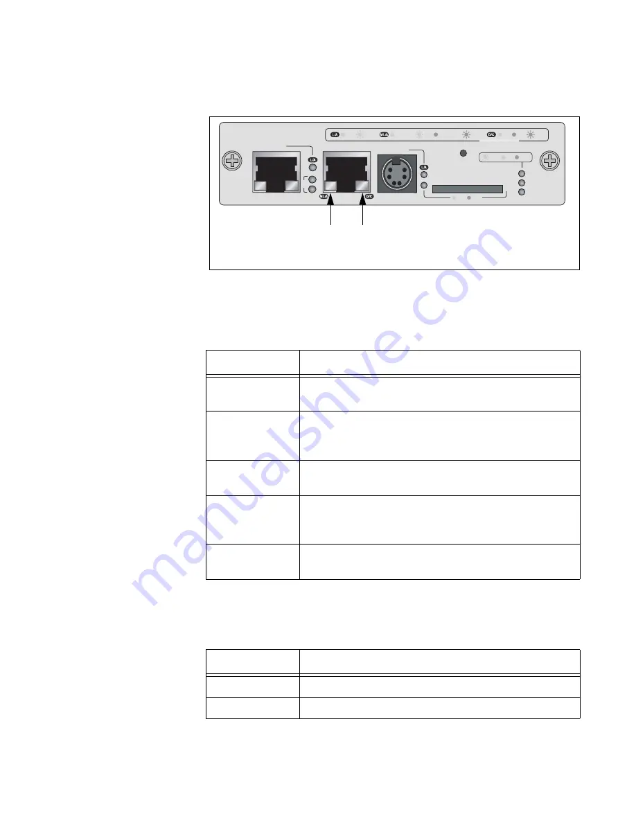
The 10/100/1000Base-T Management port has a L/A (Link/Activity) LED
and a D/C (Duplex-mode/Collisions) LED.
Figure 30. Link/Activity and Duplex-mode LEDs on the Management Port
The states of the Link/Activity LED are defined in Table 16.
The states of the Duplex-mode/Collisions LED on the Management port
are described in Table 17.
Table 16. Link/Activity LED on the Management Port
State
Description
Off
The port has not established a link with a network
device.
Steady Green
The port has established an 1000 Mbps link with a
network device, but is not forwarding or receiving
network packets.
Flashing Green
The port is forwarding or receiving network packets at
1000 Mbps.
Steady Amber
The port has established a 10 or 100 Mbps link with a
network device, but is not forwarding or receiving
network packets.
Flashing Amber
The port is forwarding or receiving network packets at
10 or 100 Mbps.
Table 17. Duplex-mode/Collisions LED on the Management Port
State
Description
Steady Green
The port is operating in full-duplex mode.
Steady Amber
The port is operating in half-duplex mode.
AT-MCF2000M
STACK
MANAGEMENT
TERMINAL
10/100/1000BASE-T
RS-232
RESET
SD
RDY
BUSY
MASTER
POWER
BOOT
RDY
FAULT
1000 LINK
ACT
10/100 LINK
ACT
FDX
HDX
COL
LINK
ACT
PORT ACTIVITY
1421
SYSTEM
ID
31
0
Link/Activity
LED
Duplex-mode
and Collisions
LED
Summary of Contents for AT-MCF2000
Page 8: ...Contents 8...
Page 12: ...Tables 12...
Page 18: ...Preface 18...
Page 20: ...20 Section I Features...
Page 26: ...Chapter 1 AT MCF2000 Multi channel Media Converter Series 26 Section I Features...
Page 54: ...Chapter 3 AT MCF2012LC AT MCF2012LC 1 and AT MCF2032SP Modules 54 Section I Features...
Page 72: ...Chapter 4 AT MCF2000M Management Module 72 Section I Features...
Page 84: ...Chapter 5 AT MCF2000S Stacking Module 84 Section I Features...
Page 86: ...86 Section II Installation...
Page 90: ...Chapter 6 Reviewing the Safety Precautions 90 Section II Installation...
Page 92: ...Chapter 7 Selecting a Location 92 Section II Installation...
Page 96: ...Chapter 8 Unpacking the AT MCF2000 or AT MCF2300 Chassis 96 Section II Installation...
Page 98: ...Chapter 9 Removing the Rubber Feet 98 Section II Installation...
Page 106: ...Chapter 11 Installing the AT MCF2KFAN Module 106 Section II Installation...
Page 110: ...Chapter 12 Installing a Media Converter Module 110 Section II Installation...
Page 122: ...Chapter 15 Installing the Chassis in an Equipment Rack 122 Section II Installation...
Page 128: ...Chapter 17 Installing the SFP Modules in the AT MCF2032SP Module 128 Section II Installation...
Page 130: ...Chapter 18 Cabling the Ports on the Media Converter Module 130 Section II Installation...
Page 134: ...Chapter 19 Cabling the AT MCF2000M and AT MCF2000S Modules 134 Section II Installation...
Page 138: ...Chapter 20 Powering on the Chassis 138 Section II Installation...
Page 156: ...Chapter 23 Troubleshooting the Modules 156 Section II Installation...
Page 186: ...Appendix C Cleaning Fiber Optic Connectors 186...
Page 190: ...Index 190...


