background image

Chapter 3: AT-MCF2012LC, AT-MCF2012LC/1 and AT-MCF2032SP Modules

52

Section I: Features

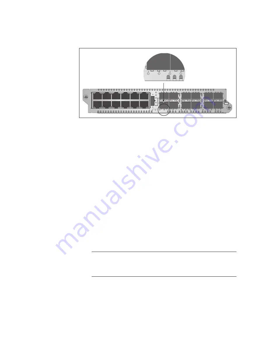
Channel selection on the AT-MCF2032SP Module is indicated with the 
row of numbered LEDs beneath the SFP slots.

Figure 23. Channel LEDs on the AT-MCF2032SP Module

You can select only one channel at a time. After you’ve selected a 
channel, the CDC and FDC LEDs reflect the duplex mode settings and the 
collisions of the channel’s two ports.

To set the operating mode of a channel, press the middle of the button to 
toggle the channel between Link Test (LT), MissingLink (ML), and Smart 
MissingLink (SML) modes. The operating mode of a channel is reflected 
by the LT, ML, and SML LEDs. A change to the operating mode is 
immediately activated on a channel.

Here is an example on how to use the Mode button. Let’s assume that you 
wanted to determine the duplex modes of the two ports in channel 8 (i.e., 
twisted pair port 8 and fiber optic port 8) and to change the operating 
mode of the channel to the Link Test mode. You first select channel 8 by 
turning the Mode button up or down to toggle the channel LEDs until the 
CH8 LED under fiber optic port 8 or, in the case of the AT-MCF2032SP 
Module, the 8 LED is on. At that point the CDC and FDC LEDs reflect the 
duplex modes and collisions of the two ports of channel 8. To change the 
operating mode of the channel to the Link Test mode, you press the button 
to toggle the operating mode LEDs until the LT LED is on.

Note

Using the Mode button to view the CDC and FDC LEDs or to change 
the operating modes of the channels on a module does not affect 
the operations of the channels.

CH

CH

CDC

FDC

LT

ML

L

A

1

L

A

2

3

4

5

6

7

8

9

10

11

12

L

A

L

A

A

T

-MCF2032SP

CLASS 1

LASER PRODUCT

SML

1

2

3

4

5

6

7

8

9

10

11

12

RDY/FLT

HBI

HBO

1

2

3

4

Summary of Contents for AT-MCF2000

Page 1: ...001052 Rev A AT MCF2000 Multi channel Media Converter Series Fast and Gigabit Ethernet Media Converter Modules AT MCF2012LC AT MCF2012LC 1 AT MCF2032SP Enclosures AT MCF2000 AT MCF2300 Installation Gu...

Page 2: ...espective owners Allied Telesis Inc reserves the right to make changes in specifications and other information contained in this document without prior written notice The information provided herein i...

Page 3: ...es uses and can radiate radio frequency energy and if not installed and used in accordance with this instruction manual may cause harmful interference to radio communications Operation of this equipme...

Page 4: ...ymbol indicates that a translation of the safety statement is available in the PDF document titled Translated Safety Statements 613 000990 posted on the Allied Telesis website at www alliedtelesis com...

Page 5: ...d AT MCF2032SP Modules 31 Overview 32 Front Panels 33 Media Converter Channels 34 Twisted Pair Ports 35 Fiber Optic Ports 36 Channel Operating Modes 37 Link Test Mode 37 MissingLink Mode 37 Smart Miss...

Page 6: ...ing the AT MCF2000AC or AT MCF2300AC Power Supply Module 99 Chapter 11 Installing the AT MCF2KFAN Module 103 Chapter 12 Installing a Media Converter Module 107 Chapter 13 Installing the AT MCF2000M Ma...

Page 7: ...e 168 Appendix A Technical Specifications 171 Environmental Specifications 171 Standards 171 Safety and Electromagnetic Emissions Certifications 172 AT MCF2000 Chassis 172 AT MCF2300 Chassis 172 AT MC...

Page 8: ...Contents 8...

Page 9: ...e Button 51 Figure 22 CH Channel LEDs on the AT MCF2012LC and AT MCF2012LC 1 Modules 51 Figure 23 Channel LEDs on the AT MCF2032SP Module 52 Figure 24 AT MCF2000M Management Module 56 Figure 25 Front...

Page 10: ...S Stacking Modules 133 Figure 78 Setting the ON OFF Switch to the OFF Position 135 Figure 79 Raising the Retaining Clip 135 Figure 80 Connecting the AC Power Cord 136 Figure 81 Positioning the Power C...

Page 11: ...rt 71 Table 19 SD Slot LED 71 Table 20 Cable Requirements for the Stack Ports 77 Table 21 LEDs on the AT MCF2000S Stacking Module 81 Table 22 AT MCF2000 Chassis Items 93 Table 23 AT MCF2300 Chassis It...

Page 12: ...Tables 12...

Page 13: ...abit Ethernet media converter products In this guide you ll learn about the features of the product and how to install the components This preface contains the following sections How this Guide is Org...

Page 14: ...xisting system go straight to the appropriate chapters Here are the sections chapters and appendices in this guide Section I Features Chapter 1 AT MCF2000 Multi channel Media Converter Series on page...

Page 15: ...s on the Media Converter Module on page 129 Chapter 19 Cabling the AT MCF2000M and AT MCF2000S Modules on page 131 Chapter 20 Powering on the Chassis on page 135 Chapter 21 Verifying the Installation...

Page 16: ...16 Where to Find Web based Guides The installation and user guides for all of the Allied Telesis products are available for viewing in portable document format PDF from our web site at www alliedtele...

Page 17: ...A numbers A product sent to Allied Telesis without an RMA number will be returned to the sender at the sender s expense To obtain an RMA number contact the Allied Telesis Technical Support group at ww...

Page 18: ...Preface 18...

Page 19: ...r 1 AT MCF2000 Multi channel Media Converter Series on page 21 Chapter 2 AT MCF2000 and AT MCF2300 Chassis on page 27 Chapter 3 AT MCF2012LC AT MCF2012LC 1 and AT MCF2032SP Modules on page 31 Chapter...

Page 20: ...20 Section I Features...

Page 21: ...networks into a central location over fiber optic cable The main components of the product are three high density 12 channel media converter modules Each channel on the modules functions as an indepe...

Page 22: ...ule It has twelve independent channels that feature 10 100Base TX twisted pair ports and 100Base FX fiber optic ports The fiber optic ports on this module have a greater operating distance up to 20 ki...

Page 23: ...t stacking module lets you daisy chain the media converter units together so that you can manage them simultaneously from one AT MCF2000M Management Card AT MCF2000AC This is the power supply module f...

Page 24: ...r modules for redundancy AT MCF2KFAN This is the cooling module for the AT MCF2000 Chassis This module is required if the chassis has just one AT MCF2000AC Power Supply Module AT MCF2300FAN This is th...

Page 25: ...000S Stacking Module does not have management software Table 2 Management Software Management Software Description AT S85 This is the management software for the AT MCF2012LC AT MCF2012LC 1 and AT MCF...

Page 26: ...Chapter 1 AT MCF2000 Multi channel Media Converter Series 26 Section I Features...

Page 27: ...0 Chassis are illustrated in Figure 1 Figure 1 AT MCF2000 and AT MCF2300 Chassis AT M CF 20 00 1 2 1415 AT MCF2KPNL1 AT MCF2KPNL1 AT MCF2000 AT M CF2 00 0 1388 AT MCF200 3 4 AT MCF2KPNL1 AT MCF2KPNL1...

Page 28: ...e for the AT MCF2000AC Power Supply Module and the AT MCF2KFAN Module The power requirements of the chassis can be met with a single power supply module A second power supply module can be installed f...

Page 29: ...0 Chassis Slots Slot Module Module 1 to 4 These slots are for the multi channel AT MCF2012LC AT MCF2012LC 1 and AT MCF2032SP Media Converter Modules Each slot can accommodate one module Management Slo...

Page 30: ...he unit they load share the power requirements of the chassis Management This slot is for the optional AT MCF2000M Management Module or the AT MCF2000S Stacking Module AT MCF2300FAN This is a preinsta...

Page 31: ...e following sections Overview on page 32 Front Panels on page 33 Media Converter Channels on page 34 Twisted Pair Ports on page 35 Fiber Optic Ports on page 36 Channel Operating Modes on page 37 Port...

Page 32: ...prevent the propagation of incomplete or fragmented packets on your network Figure 4 AT MCF2000 Series Media Converter Module The standards and features of the modules are listed here IEEE 802 3 10Bas...

Page 33: ...Front Panel of the AT MCF2032SP Module L A L A CH CH CH1 CH2 L A L A CH3 CH4 L A L A CH5 CH6 L A L A CH7 CH8 L A L A CH9 CH10 L A L A CH11 CH12 TX RX 1 TX RX TX RX TX RX 2 3 4 5 6 7 8 9 10 11 12 CDC...

Page 34: ...e network devices that need to forward traffic to each other through the media converter module have to be connected to ports in the same channel For example for a local Fast Ethernet switch to commun...

Page 35: ...he ports on the network devices The auto MDI MDI X feature is only available when the twisted pair ports are using Auto Negotiation the default setting If you disable Auto Negotiation on a port and se...

Page 36: ...ill be significantly less For the operating specifications of the fiber optic ports on the AT MCF2012LC and AT MCF2012LC 1 Modules refer to 100Base FX Fiber Optic Ports on page 175 For the fiber optic...

Page 37: ...rk operations It is typically used when the network devices connected to a channel cannot take advantage of the features of the MissingLink mode or when you want to use the Link LEDs to troubleshoot a...

Page 38: ...nning a spanning tree protocol or sending an SNMP trap to a management workstation if it is using SNMP Without the MissingLink mode Switch B would assume that it still had a valid link to the remote d...

Page 39: ...MissingLink mode works Assume that the fiber optic port in a media converter channel lost its link to its network device while the channel was in the Smart MissingLink operating mode The mode would r...

Page 40: ...action such as sending out SNMP traps Allied Telesis does not recommend using the Smart MissingLink mode on a channel that is connected to managed devices As explained in Smart MissingLink Mode on pa...

Page 41: ...d the bottom right corners of the lower ports Figure 9 Activity LED for a Twisted Pair Port The Activity LEDs for the fiber optic ports on the AT MCF2012LC and the AT MCF2012LC 1 Modules are located t...

Page 42: ...e or the LT ML and SML LEDs and the Mode button on the front panel of a module It can also be useful to consider the Link LEDs of the two ports of a channel as a pair and to view them as a unit The me...

Page 43: ...es to the lower SFP module and the second Link LED applies to the upper module Figure 14 Link LEDs for the Fiber Optic Ports on the AT MCF2032SP Module Link LED Colors The Link LEDs for the twisted pa...

Page 44: ...result the Link LEDs of the ports also work in tandem As described in Table 9 the Link LEDs will be on if both ports can establish links to their network devices and they will if off if one or both p...

Page 45: ...ts Link LED States Description Twisted Pair Port Off One or both ports in the channel can not establish links with their network devices Fiber Optic Port Off Twisted Pair Port Steady Green or Amber Bo...

Page 46: ...isted pair port 4 and fiber optic port 4 For more information refer to Mode Button on page 51 Twisted Pair Port Off The fiber optic port in the channel can establish a link with its network device but...

Page 47: ...A L A CH CH CH1 CH2 L A L A CH3 CH4 L A L A CH5 CH6 L A L A CH7 CH8 L A L A CH9 CH10 L A L A CH11 CH12 TX RX 1 TX RX TX RX TX RX 2 3 4 5 6 7 8 9 10 11 12 CDC FDC LT ML SML L A 1 L A 2 3 4 5 6 7 8 9 1...

Page 48: ...ons LEDs LED State Description CDC Off The twisted pair port in the channel has not established a link with its network device Steady Green The twisted pair port is operating in full duplex mode Stead...

Page 49: ...possible states of the LED CH CH FDC LT ML SML CH CH CDC FDC LT ML L A 1 L A 2 3 4 5 6 7 8 9 10 11 12 L A L A AT MCF2032SP CLASS 1 LASER PRODUCT SML 1 2 3 4 5 6 7 8 9 10 11 12 RDY FLT HBI HBO Table 1...

Page 50: ...to view duplex modes and collisions The channel LEDs on the AT MCF2012LC 1 Media Converter Modules are located below the fiber optic ports and are labeled CH The channel LEDs on the AT MCF2012LC Modu...

Page 51: ...MCF2012LC and AT MCF2012LC 1 Modules is indicated by the numbered CH LEDs in the bottom right corners of the fiber optic ports Figure 22 CH Channel LEDs on the AT MCF2012LC and AT MCF2012LC 1 Modules...

Page 52: ...n Let s assume that you wanted to determine the duplex modes of the two ports in channel 8 i e twisted pair port 8 and fiber optic port 8 and to change the operating mode of the channel to the Link Te...

Page 53: ...e the port assignments of the channels You can use the media converter channels in any order The twisted pair port and the fiber optic port of a channel can operate at different speeds provided that t...

Page 54: ...Chapter 3 AT MCF2012LC AT MCF2012LC 1 and AT MCF2032SP Modules 54 Section I Features...

Page 55: ...ribes the optional AT MCF2000M Management Module Overview on page 56 Front Panel on page 58 10 100 1000Base T Management Port on page 59 RS 232 Terminal Port on page 61 Stack Port on page 62 Reset But...

Page 56: ...ule to manage more than media converter chassis at a time Note The AT MCF2000M Management Module is optional The AT MCF2000 Media Converter Modules can be used as unmanaged devices Figure 24 AT MCF200...

Page 57: ...ages Send the event messages to a syslog server Manage up to sixteen media converter modules from one management module Create additional manager accounts Download new versions of the management softw...

Page 58: ...remote in band management from a Telnet or Secure Shell SSH client and file transfers to or from a TFTP server For further information refer to 10 100 1000Base T Management Port on page 59 RS 232 Term...

Page 59: ...Management Protocol SNMP traps to an SNMP management program The port has a standard RJ 45 8 pin connector and can operate at 10 100 or 1000 Mbps in either half or full duplex mode The cable requireme...

Page 60: ...uration of the end node This allows you to use a straight through twisted pair cable regardless of the wiring configuration of the port on the network device The auto MDI MDI X feature is only availab...

Page 61: ...require the module to have an Internet Protocol IP address is referred to as local or out of band management because it is not conducted over a network This type of management uses the RS 232 Serial...

Page 62: ...tures Stack Port You use the Stack port to connect the chassis to another chassis that has the AT MCF2000S Stacking Module so that you can manage the units simultaneously For background information re...

Page 63: ...e AT S97 Management Software To determine when the module has completed the initialization process view the general status LEDs on the module For information refer to General Status LEDs on page 67 No...

Page 64: ...atures Figure 26 Pressing the Reset Button 1203b AT MCF2000M STACK MANAGEMENT TERMINAL 10 100 1000BASE T RS 232 RESET SD RDY BUSY MASTER POWER BOOT RDY FAULT 1000 LINK ACT 10 100 LINK ACT FDX HDX COL...

Page 65: ...ansferring the master configuration file with a secure digital memory card A secure digital memory card is optional The management module can operate without a memory card For information on using a s...

Page 66: ...fault setting is 0 For more information refer to Chassis ID Numbers on page 79 Figure 27 Chassis ID Jumper Note You cannot change the chassis ID number with the AT S97 Management Software AT MCF2000M...

Page 67: ...izing the AT S97 Management Software and loading its active master configuration file Amber The management module has experienced a fault condition Flashing Amber The management module is receiving a...

Page 68: ...odule is receiving power Table 14 General Status LEDs Continued LED State Description Table 15 Link Activity LED on the RS 232 Terminal Port State Description Off This LED setting is reserved for futu...

Page 69: ...0 Mbps link with a network device but is not forwarding or receiving network packets Flashing Green The port is forwarding or receiving network packets at 1000 Mbps Steady Amber The port has establish...

Page 70: ...Number LEDs Stack Port LED The L A Link Activity LED on the Stack port is shown in Figure 32 Figure 32 Link Activity LED on the Stack Port Flashing Amber The port is operating in half duplex mode with...

Page 71: ...f a stack or the port has not established a link with the Stack port in another chassis Steady Green The port has established a link with the Stack port in the next chassis in the stack Flashing Green...

Page 72: ...Chapter 4 AT MCF2000M Management Module 72 Section I Features...

Page 73: ...0S Stacking Module The sections in the chapter are Overview on page 74 Topology on page 75 Maximum Number of Media Converter Modules in a Stack on page 76 Cabling the Stack Ports on page 77 Chassis ID...

Page 74: ...r building there is an alternative You could instead link the units together with the AT MCF2000S Stacking Module to form a management stack This feature lets you monitor and configure the units with...

Page 75: ...tes a stack of four media converter chassis Figure 35 Example Stack of Four Media Converter Chassis The maximum cable length is 100 meters making it possible for you to create stacks of devices locate...

Page 76: ...mple the maximum size of a stack of the AT MCF2000 Chassis which has two slots for media converter modules is eight enclosures 8 AT MCF2000 Chassis x 2 slots 16 media converter modules In contrast the...

Page 77: ...ing Distance Standard straight through or crossover TIA EIA 568 B compliant Enhanced Category 5 Cat 5e shielded or unshielded cabling with 100 ohm impedance 100 m 328 ft AT MCF2000S LINK ACT PORT ACTI...

Page 78: ...T PORT ACTIVITY STACK 1 STACK 2 CHASSIS ID AT MCF2000S LINK ACT PORT ACTIVITY STACK 1 STACK 2 CHASSIS ID AT MCF2000S LINK ACT PORT ACTIVITY STACK 1 STACK 2 CHASSIS ID AT MCF2000S LINK ACT PORT ACTIVIT...

Page 79: ...ck and you want to assign the second management card the value 31 Otherwise there is no reason to change the chassis ID number of a management card from the default value of 0 Note At the time this ma...

Page 80: ...ll find the units easier to identify and so reduce the chance of performing a configuration command on the wrong device if you have a numbering scheme Figure 41 is an example of a stack of four AT MCF...

Page 81: ...d in this table Table 21 LEDs on the AT MCF2000S Stacking Module State Description Off The port has not established a link with a Stack port on another stacking module Steady green The port has establ...

Page 82: ...AT MCF2000S Stacking Module 82 Section I Features Chassis ID LEDs The Chassis ID LEDs display the ID number assigned to the module with the DIP switches For information refer to Chassis ID Numbers on...

Page 83: ...ed in the units because they are not accessible afterwards The ID numbers of the units in a stack do not have to be sequential or reflect the numerical positions of the chassis in the daisy chain topo...

Page 84: ...Chapter 5 AT MCF2000S Stacking Module 84 Section I Features...

Page 85: ...ge 107 Chapter 13 Installing the AT MCF2000M Management Module on page 111 Chapter 14 Installing the AT MCF2000S Stacking Module on page 115 Chapter 15 Installing the Chassis in an Equipment Rack on p...

Page 86: ...86 Section II Installation...

Page 87: ...laser products or Class1 LED products Warning Class 1 Laser product L1 AT MCF2012LC 1 Module Warning Do not stare into the laser beam L2 Class 1 LED product L3 AT MCF2012LC Module Warning The fiber op...

Page 88: ...us voltages on accessible metal parts E4 Pluggable Equipment The socket outlet shall be installed near the equipment and shall be easily accessible E5 Caution Air vents must not be blocked and must ha...

Page 89: ...E22 Warning Mounting of the equipment in the rack should be such that a hazardous condition is not created due to uneven mechanical loading E25 Warning Remove all metal jewelry such as rings and watch...

Page 90: ...Chapter 6 Reviewing the Safety Precautions 90 Section II Installation...

Page 91: ...ar vents should be unrestricted Do not place objects on top of the chassis Do not expose the device to moisture or water Make sure that the site is in a dust free environment Use dedicated power circu...

Page 92: ...Chapter 7 Selecting a Location 92 Section II Installation...

Page 93: ...r Allied Telesis sales representative for assistance Note You should retain the original packaging material in the event you ever need to return the unit to Allied Telesis Table 22 lists the items shi...

Page 94: ...One Installation and User Documentation CD Table 23 AT MCF2300 Chassis Items Component Description One AT MCF2300 Chassis One AT MCF2300FAN Module preinstalled Table 22 AT MCF2000 Chassis Items Compon...

Page 95: ...ation 95 Two rack mount brackets Eight rack mount bracket screws One fan cover preinstalled Seven blank slot covers preinstalled One grounding lug One Installation and User Documentation CD Table 23 A...

Page 96: ...Chapter 8 Unpacking the AT MCF2000 or AT MCF2300 Chassis 96 Section II Installation...

Page 97: ...be possible to install the enclosure closer to the device below it thus allowing you to install more devices in the rack To remove the rubber feet 1 Place the unit upside down on a level secure surfac...

Page 98: ...Chapter 9 Removing the Rubber Feet 98 Section II Installation...

Page 99: ...er Supply Modules or one AT MCF2000AC Module and one AT MCF2KFAN Module This procedure uses the AT MCF2000 Chassis for illustration purposes For the locations of the power supply slots on the AT MCF23...

Page 100: ...lied Telesis sales representative for assistance Note You should retain the original packaging material in the event you need to return the unit to Allied Telesis Table 24 AT MCF2000AC or AT MCF2300AC...

Page 101: ...anel in the chassis Caution To prevent damaging the connector pins on the backplane do not force the module into place Figure 44 Installing the AT MCF2000AC Power Supply Module 4 Secure the power supp...

Page 102: ...holes in the bracket Figure 46 Installing a Retaining Clip 6 If the chassis will have two power supplies repeat this procedure to install the second module If you are assembling an AT MCF2300 Chassis...

Page 103: ...d does not use the AT MCF2KFAN Module The AT MCF2KFAN Module supports hot swapping and can installed or replaced while the chassis is powered on To install the AT MCF2KFAN Module 1 Remove the AT MCF2K...

Page 104: ...s sales representative for assistance Note You should retain the original packaging material in the event you need to return the unit to Allied Telesis Note The AT MCF2KFAN Module does not have a powe...

Page 105: ...tion To avoid damaging the connector pins on the backplane do not force the module into place Figure 48 Installing the AT MCF2KFAN Fan Module 4 Secure the fan module to the chassis by tightening the t...

Page 106: ...Chapter 11 Installing the AT MCF2KFAN Module 106 Section II Installation...

Page 107: ...a grounding device and observe electrostatic discharge precautions when installing the module in the chassis This procedure uses the AT MCF2000 Chassis for illustration purposes For the locations of...

Page 108: ...turn the unit to Allied Telesis 3 Remove the insulator labelled REMOVE BEFORE INSTALL from the battery on the media converter module by sliding it out from beneath the battery clip Figure 51 Removing...

Page 109: ...ion Do not force the module into place If there is resistance remove the module verify that the edges of the card are properly aligned in the guides in the chassis module slot and reinsert it Figure 5...

Page 110: ...Chapter 12 Installing a Media Converter Module 110 Section II Installation...

Page 111: ...scharge precautions when installing the module in the chassis This procedure uses the AT MCF2000 Chassis for illustration purposes For the location of the Management slot on the AT MCF2300 Chassis ref...

Page 112: ...in the stack you can leave the jumper at the default setting For background information refer to Chassis ID Jumper on page 66 or the AT S85 and AT S97 Management Software Command Line User s Guide No...

Page 113: ...y clip Figure 56 Removing the Battery Insulator AT MCF2000M STACK MANAGEMENT TERMINAL 10 100 1000BASE T RS 232 RESET SD RDY BUSY MASTER POWER BOOT RDY FAULT 1000 LINK ACT 10 100 LINK ACT FDX HDX COL L...

Page 114: ...d are properly aligned in the guides in the chassis module slot Figure 57 Installing the Management Module 6 Secure the management module to the chassis by tightening the two captive screws on the mod...

Page 115: ...charge precautions when installing the module in the chassis This procedure uses the AT MCF2000 Chassis for illustration purposes For the location of the Management slot on the AT MCF2300 Chassis refe...

Page 116: ...er s Guide The ID number is set with switches 1 to 5 Switch 6 is not used If there is tape on the DIP switches remove the tape To set the switches use a pointed object such as the tip of a ball point...

Page 117: ...he module on the connector on the back panel in the chassis Caution Do not force the module into place If there is resistance remove the module and before reinserting it verify that the edges of the c...

Page 118: ...ep 3 You ll use the label during the verification process later in this manual to verify the ID number of the module The label will also be useful in identifying the module s chassis ID number wheneve...

Page 119: ...ard 19 inch equipment rack 1 Attach a rack mount bracket to one side of the chassis using four of the screws included with the unit Figure 64 Attaching a Rack mount Bracket to the AT MCF2000 Chassis F...

Page 120: ...essed one or two inches You can also install the unit so that it extends two inches from the front of the rack The various bracket positions are illustrated in Figure 66 the symbols identify the appro...

Page 121: ...hazard because they extend beyond the equipment rack and the chassis Figure 67 Invalid Rack mount Bracket Positions on the AT MCF2300 Chassis 2 Install the second rack mount bracket on the other side...

Page 122: ...Chapter 15 Installing the Chassis in an Equipment Rack 122 Section II Installation...

Page 123: ...ill depend on your installation Crimping tool Grounding lug included with the chassis To ground the AT MCF2300 Chassis 1 Strip the grounding wire as shown in Figure 68 Figure 68 Stripping the Groundin...

Page 124: ...Lug Screws 4 Attach the grounding lug to the back panel of the chassis using the two screws removed in the previous step Figure 71 Attaching the Grounding Lug 5 Attach the other end of the grounding w...

Page 125: ...ptic cables are not installed or when you store the transceivers When you do remove a dust plug keep it for future use Unnecessary removal and insertion of SFP modules can lead to premature failure of...

Page 126: ...ed in a slot in the top row position it with the label facing up If the transceiver is being installed in a slot in the bottom row position it with the label facing down 4 Slide the transceiver into t...

Page 127: ...ection II Installation 127 Note Do not remove the dust cap from an SFP transceiver until you are ready to connect a fiber optic cable Dust contamination can adversely affect a fiber optic port 6 Repea...

Page 128: ...Chapter 17 Installing the SFP Modules in the AT MCF2032SP Module 128 Section II Installation...

Page 129: ...s to the fiber optic ports Do not remove the dust cover from a fiber optic port until you are ready to connect the cable Dust contamination can adversely affect the operation of the port The connector...

Page 130: ...Chapter 18 Cabling the Ports on the Media Converter Module 130 Section II Installation...

Page 131: ...to the 10 100 1000Base T Management port Connect the other end of the cable to a network device such as a Fast Ethernet or Gigabit Ethernet switch For background information refer to 10 100 1000Base...

Page 132: ...ed Category 5 Cat 5e shielded or unshielded cabling with 100 ohm impedance Connect one of the Stack ports on one module to either of the Stack ports on the module in the next chassis All port combinat...

Page 133: ...CTIVITY STACK 1 STACK 2 CHASSIS ID AT MCF2000S LINK ACT PORT ACTIVITY STACK 1 STACK 2 CHASSIS ID AT MCF2000S LINK ACT PORT ACTIVITY STACK 1 STACK 2 AT MCF2000S LINK ACT PORT ACTIVITY STACK 1 STACK 2 C...

Page 134: ...Chapter 19 Cabling the AT MCF2000M and AT MCF2000S Modules 134 Section II Installation...

Page 135: ...er to the AT MCF2000 or AT MCF2300 Chassis 1 Set the ON OFF switch on the module to the OFF position Figure 78 Setting the ON OFF Switch to the OFF Position 2 Raise the retaining clip to the upright p...

Page 136: ...etaining Clip 5 Plug the other end of the power cord into an appropriate power source For the power requirements refer to AT MCF2000AC Power Supply Module on page 173 or AT MCF2300AC Power Supply Modu...

Page 137: ...erter chassis has two power supplies you can protect it from a power circuit failure by connecting the power cords to outlets on different circuits This completes the installation procedure For instru...

Page 138: ...Chapter 20 Powering on the Chassis 138 Section II Installation...

Page 139: ...after the initial installation of the chassis or whenever you add or replace modules The sections are AT MCF2000AC and AT MCF2300AC Power Supply Module on page 140 AT MCF2KFAN and AT MCF2300FAN Modul...

Page 140: ...r to AT MCF2000AC and AT MCF2300AC Power Supply Modules on page 150 for troubleshooting suggestions AT MCF2KFAN and AT MCF2300FAN Modules To verify the status of the AT MCF2KFAN Module Verify that the...

Page 141: ...ddle of the Mode button until the LT LED is on 3 Observe the Link LEDs of the twisted pair and fiber optic ports of the channel If the Link LEDs for both of the ports in the channel are on the ports h...

Page 142: ...shing green If you encounter any problems refer to AT MCF2000M Management Module on page 153 AT MCF2000S Stacking Module To verify the installation of the optional AT MCF2000S Stacking Module View the...

Page 143: ...le to the RS 232 Terminal Port 2 Connect the DB 9 connector on the management cable to an RS 232 port on a terminal or a PC with a terminal emulator program 3 Configure the terminal or terminal emulat...

Page 144: ...anager account on the management module There is a predefined manager account that allows access to all of the parameters on the management and media converter modules This account has the user name m...

Page 145: ...solve it with the information in the following sections AT MCF2012LC AT MCF2012LC 1 and AT MCF2032SP Media Converter Modules on page 146 AT MCF2000AC and AT MCF2300AC Power Supply Modules on page 150...

Page 146: ...the LT ML and SML LEDs on the module One of the LEDs should be on as well one of the channel LEDs If the LEDs are off the module is not receiving power or has failed Try the following Remove the media...

Page 147: ...nel is off but the Link LED of the twisted pair port is on or blinking Solution The fiber optic port is unable to establish a link to a network device Try the following Verify that the network device...

Page 148: ...naged devices use their management firmware to determine whether they are configured and operating properly If the network devices are using a spanning tree protocol the ports on the devices may have...

Page 149: ...m 9 A channel is operating in the Smart MissingLink mode and the Link LEDs for both ports are blinking Solution This can have several possible causes One possible cause is if the channel is connected...

Page 150: ...meets the operating specifications of the power supply module listed in AT MCF2000AC Power Supply Module on page 173 and AT MCF2300AC Power Supply Module on page 173 Replace the power supply module P...

Page 151: ...n in the module has failed Replace the module Problem 3 The three FAN LEDs on the AT MCF2300FAN Module are off Solution The fan module is not receiving power or has failed Try the following Verify tha...

Page 152: ...Chapter 23 Troubleshooting the Modules 152 Section II Installation Figure 84 Covering a Broken Fan on the AT MCF2300FAN Module 1394 000FAN FAN 1 FAN 2 FAN 3 1395 000FAN FAN 1 FAN 2 FAN 3...

Page 153: ...cable is securely connected to the port on the management module and on the network device Verify that you are using the correct type of cable for the port and have not exceeded the maximum length Ref...

Page 154: ...LED is on but you are unable to start a remote Telnet or SSH management session with the management module Solution Try the following Start a local management session on the management module and usi...

Page 155: ...000S Module Replace the module If the replacement module works the problem is with the original module If the replacement module does not work the problem is with the chassis Problem 2 A cable is conn...

Page 156: ...Chapter 23 Troubleshooting the Modules 156 Section II Installation...

Page 157: ...161 Replacing the AT MCF2000AC or AT MCF2300AC Power Supply on page 164 Replacing the AT MCF2300FAN Module on page 168 Note All of the modules in the AT MCF2000 Series support hot swapping You do not...

Page 158: ...dling the modules To remove a media converter module 1 Label and disconnect all of the twisted pair cables and the fiber optic cables from the ports on the module The labels will make it easier for yo...

Page 159: ...he SFP modules Figure 87 Removing the SFP Modules from the AT MCF2032SP Module 4 Using a cross head screwdriver loosen the two captive screws that secure the module to the chassis and slide the module...

Page 160: ...ment module or is part of a stack the settings on the replacement module are configured by the management module to match the previous module For further information refer to the AT S85 and AT S97 Man...

Page 161: ...ectrostatic discharge precautions when handling the modules 1 Disconnect all of the cables from the ports on the module Figure 90 Disconnecting the Cables from the AT MCF2000M and AT MCF2000S Modules...

Page 162: ...apter 13 Installing the AT MCF2000M Management Module on page 111 or Chapter 14 Installing the AT MCF2000S Stacking Module on page 115 AT MCF2000M STACK MANAGEMENT TERMINAL 10 100 1000BASE T RS 232 RE...

Page 163: ...If you are not installing a replacement module position the AT MCF2KPNL3 Slot Cover and secure it with the two captive screws Figure 92 Installing the AT MCF2KPNL3 Slot Cover on the Management Slot AT...

Page 164: ...0AC Power Supply To remove or replace the AT MCF2000AC or AT MCF2300AC Power Supply 1 Set the ON OFF switch on the module to the OFF position Figure 93 Setting the ON OFF Switch to the OFF Position 2...

Page 165: ...lation Guide Section II Installation 165 3 Raise the retaining clip and disconnect the power cord from the module Figure 94 Removing the Power Cord AT MCF2KPNL3 NORMAL FAU LT STATUS PSU FAN M A AT MCF...

Page 166: ...ide the power module from the unit Figure 95 Removing the AT MCF2000AC or AT MCF2300AC Power Supply Module 5 To install another power supply refer to Chapter 10 Installing the AT MCF2000AC or AT MCF23...

Page 167: ...ion 167 6 If you are not installing a replacement module position the AT MCF2KPNL2 Slot Cover and secure it with the two captive screws Figure 96 Installing the AT MCF2KPNL2 Slot Cover over the Power...

Page 168: ...MCF2300FAN Module Otherwise the chassis may overheat which can damage the modules To replace the AT MCF2300FAN Module in the AT MCF2300 Chassis 1 If you used the fan cover to cover a broken fan remove...

Page 169: ...n 169 2 Using a cross head screwdriver loosen the two captive screws that secure the module to the chassis and remove the module from the unit Figure 98 Removing the AT MCF2300FAN Module AT M CF2000 A...

Page 170: ...r in the chassis Then secure the module by tightening the two captive screws with a cross head screwdriver Figure 99 Installing a New AT MCF2300FAN Module For instructions on how to verify the operati...

Page 171: ...ity Less than 80 noncondensing Storage Humidity Less than 95 noncondensing Maximum Operating Altitude 3 048 m 10 000 ft Maximum Non operating Altitude 4 000 m 13 000 ft Standards IEEE 802 3 10Base T I...

Page 172: ...TUV C Tick AT MCF2000 Chassis Dimensions 4 4 x 44 0 x 42 4 cm 1 75 x 17 3 x 16 7 in H x W x D Weight Chassis with blank faceplates 5 5 kg 12 0 lb Weight Chassis with two AT MCF2000AC Modules and two A...

Page 173: ...00 240 VAC 50 60 Hz Output Voltages 12 volts and 3 3 volts Maximum Input Current 2A Power Consumption 100 W maximum MTBF 140 000 AT MCF2300AC Power Supply Module Dimensions 4 1 x 13 3 x 20 6 cm 1 6 x...

Page 174: ...SP 0 78 kg 1 71 lb Input Voltage 12 volts and 3 3 volts Maximum Input Current 3 amperes Maximum Power Consumption 36 watts MTBF AT MCF2012LC and AT MCF2012LC 1 300 000 hrs MTBF AT MCF2032SP 220 000 hr...

Page 175: ...aximum Distance 2 km Fiber Optic Cable 50 125 m or 62 5 125 m core cladding multimode fiber optic cable Transmitter Wavelength 1310 nm Output Optical Power 20 dBm min 14 dBm max Receiver Wavelength 13...

Page 176: ...connector Figure 100 RJ 45 Connector and Port Pin Assignments Table 32 lists the pins signals in the MDI and MDI X configurations at 10 or 100 Mbps Table 33 lists the pin signals when the management...

Page 177: ...of the RS 232 Terminal port Figure 101 RS 232 Terminal Port Pinouts Table 34 lists the pin signals for the RS 232 Terminal port 4 Pair 3 5 Pair 3 6 Pair 2 7 Pair 4 8 Pair 4 Table 33 10 100 1000Base T...

Page 178: ...cm 1 2 x 3 8 x 8 2 in H x W x D Weight 295 g 0 65 lb MTBF 1 010 000 AT MCF2KFAN Module Dimensions 4 1 x 13 3 x 20 6 cm 1 6 x 5 3 x 8 1 in H x W x D Weight 818 g 1 8 lb MTBF 90 000 AT MCF2300FAN Module...

Page 179: ...000S Stacking Module AT MCF2000S STACK 1 LINK ACT PORT ACTIVITY STACK 2 CHASSIS ID 1400 OFF ON 6 1 CHASSIS_ID SW2 DIP Switch 1 Table 35 SW2 DIP Switch Settings ID Numbers 1 to 15 for the AT MCF2000S S...

Page 180: ...0S Stacking Module DIP Switch Chassis ID Number 16 17 18 19 20 21 22 23 24 25 26 27 28 29 30 1 off off off off off off off off off off off off off off off 2 on on on on on on on on off off off off off...

Page 181: ...to the naked eye can disrupt light transmission and lead to failure of the component or of the entire system Therefore it is of utmost importance to clean all fiber optic connectors before use Figure...

Page 182: ...using a cartridge cleaner 1 With one hand hold the cartridge cleaner and push the lever on the cleaning cartridge in the direction of the arrow to expose the cleaning surface as shown in Figure 106 o...

Page 183: ...ution Failing to pick up the ferrule tip when you reach the bottom of the cleaning surface can result in static electricity that can damage the fiber optic cable 4 If desired repeat steps 3 and 4 5 If...

Page 184: ...spectively Note NEVER use a household cotton swab and or alcohol to clean a fiber optic connector This may leave a residue on the ferrule tip Figure 107 Lint Free and Alcohol Free Swabs Note Do not us...

Page 185: ...on scope is available use the scope to inspect the connector to make sure that it is clean and to check for scratches pits or other problems that may affect performance Note Always keep a dust cap on...

Page 186: ...Appendix C Cleaning Fiber Optic Connectors 186...

Page 187: ...ID numbers 116 179 technical specifications 178 topology 75 troubleshooting 155 verifying operations 142 AT MCF2012LC Media Converter Module cabling 129 channel operating modes 37 channels 34 fiber op...

Page 188: ...82 chassis ID numbers assigning to AT MCF2000M Management Module 66 112 assigning to AT MCF2000S Stacking Modules 116 179 described 79 collision LEDs 46 D duplex mode LEDs 46 E equipment rack 119 F F...

Page 189: ...module See AT MCF2000S Stacking Module stacking topology 75 standards 171 SW2 DIP switches described 79 setting 116 179 System LED 67 T technical specifications 171 troubleshooting AT MCF2000AC Power...

Page 190: ...Index 190...

Reviews: