background image

62

505872

Section 5 Service Procedures

To reduce the risk of electric shock, fire, explosion, serious injury or death:
• Disconnect electric power to the dryer(s) before servicing.
• Close gas shut-off valve to gas dryer(s) before servicing.
• Never start the dryer(s) with any guards/panels removed.
• Whenever ground wires are removed during servicing, these ground wires must be

reconnected to ensure that the dryer is properly grounded.

W001R1

WARNING

© Copyright, Alliance Laundry Systems LLC – DO NOT COPY or TRANSMIT

g. Manually rotate cylinder until one of the baffles

is at the 6:00 position and carefully remove
cylinder out through front of dryer.

NOTE: On models using unpainted, corrosion
resistant, coated steel cylinder, the cylinder must be
installed with the side marked “FRONT” or the
arrow pointing toward front of dryer.

h. Gas Models:

(1) Disconnect igniter wires at disconnect

blocks, sensor wires from sensor terminals,
and wires from gas valve coils at the quick
disconnect blocks. Refer to Figure 19.

(2) Remove screw from right side of burner

housing, holding burner tube in place.
Refer to Figure 23.

(3) Gently move burner tube toward rear of

dryer to disengage tab from slot on left side
of burner housing. Refer to Figure 19.

(4) Carefully rotate burner tube and igniter

counterclockwise so tab is at 8 o’clock
position.

(5) More air shutter end of burner tube slightly

to right and CAREFULLY remove burner
tube and igniter assembly out through front
of dryer.

IMPORTANT: The igniter is very fragile. Be careful
not to damage it during removal.

(6) Remove screw holding burner housing to

heat shroud. Refer to Figure 19.

(7) Remove screw holding front of burner

housing to dryer base and remove housing
out through front of dryer. Refer to
Figure 23.

(8) Remove four screws holding shroud to

heater box and remove shroud out through
front of dryer. Refer to Figure 19.

i. Electric Models:

(1) Remove two screws holding element and

plate to heater box, then pull element down
and away from heater box. Refer to
Figure 23.

j. Remove screw holding heat shield to dryer

base. Refer to Figure 35.

k. Remove one screw holding rear bulkhead to

terminal block bracket. While supporting
bulkhead, remove the four screws holding rear
bulkhead to mounting brackets, then lift
complete assembly out of dryer. Refer to
Figure 35.

l. To remove heat shield from heater box:

(1) Remove two screws holding heat shield to

heater box. Refer to Figure 35.

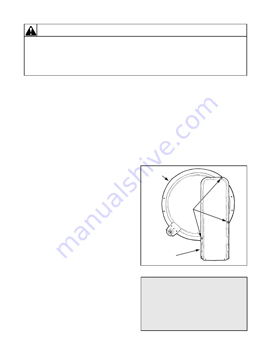
m. To remove heater box from rear bulkhead:

(1) Refer to Figure 37 for removal.

n. Rear mounting brackets:

(1) Remove five screws holding rear mounting

brackets to rear of dryer cabinet. Refer to
Figure 26.

Figure 37

DR011-SV-1

HEATER

BOX

REAR

BULKHEAD

HEATER

BOX

ATTACHING

SCREWS

To Test Heater Assembly:

(Electric Models)

1. Disconnect wires from heater assembly.

NOTE: Refer to appropriate wiring diagram
when rewiring heater assembly.

2. Set meter to read Ohms. Apply meter probes to

the heater assembly terminals. Meter should
read 10.4 Ohms ± .30 Ohms cold.

Summary of Contents for EE1010

Page 1: ...Service www comlaundry com Dryers Refer to Page 6 for Model Numbers Part No 505872R1 February 2001 DRY1C...

Page 2: ...7 Motor Mounting Bracket to Exhaust Fan Cover Gas and Electric Models with painted exhaust fan cover 21 18 Neutral at Terminal Block to Terminal Block Bracket and From Terminal Block Bracket to Contro...

Page 3: ...Procedures 65 Installing the No 458P3 Kit 72 66 Installing No 459P3 Kit 76 Section 8 Internal Wiring of Dryer Motor Switch 79 Section 9 Wiring Diagrams 81 Model EE1010 Through Serial No S6270865XG 82...

Page 4: ...ANT and NOTE are followed by specific instructions IMPORTANT The word IMPORTANT is used to inform the reader of specific procedures where minor machine damage will occur if the procedure is not follow...

Page 5: ...s also recommends contacting an authorized technician and using authorized factory parts To reduce the risk of electric shock fire explosion serious injury or death Disconnect electric power to the dr...

Page 6: ...from whom the machine was purchased or contact Alliance Laundry Systems at 920 748 3950 for the name and address of the nearest authorized parts distributor For technical assistance call 920 748 3121...

Page 7: ...RANSMIT Model Identification Information in this manual is applicable to these dryers Model Numbers Nonmetered Models Metered Models Card Models Audit Models Electric Heat Gas Heat EE1010 X X EG1020 X...

Page 8: ...t fan pulls air in through louvers at the rear of the dryer and over the heat source burner flame for gas and heating element for electric The heated air moves through the heater duct and into the cyl...

Page 9: ...eatedly refer to Paragraph 2 Timer improperly set nonmetered models Reset timer Inoperative motor switch Test switch and replace if inoperative Start circuit non completed Press start switch button or...

Page 10: ...drive pulley loose Tighten setscrew Figure 29 Broken cylinder belt Replace belt Cylinder belt is upside down or twisted Install properly Clothes cylinder is binding Check cylinder for binding and out...

Page 11: ...ative limit thermostat Test thermostat and replace if inoperative Electric Models Inoperative heating element Replace element Gas Models Insufficient gas supply Open partially closed gas shut off valv...

Page 12: ...supply Check gas supply and pressure Make sure gas shut off valve is open POSSIBLE CAUSE TO CORRECT Improper or inadequate exhaust system Refer to Installation Instructions supplied with dryer for ex...

Page 13: ...external exhaust system Disassemble and clean exhaust system Hinged damper on exhaust system weather hood not free to open Free hinged damper or replace weather hood Limit thermostat cycling at too l...

Page 14: ...t the dryer is properly grounded W001R1 WARNING Copyright Alliance Laundry Systems LLC DO NOT COPY or TRANSMIT 14 CLOTHES ARE TOO HOT WHEN REMOVED FROM DRYER POSSIBLE CAUSE TO CORRECT Clothes are remo...

Page 15: ...TERIZED AUDIT MODELS B A C D E F HS 1 RS 1 1 2 3 4 1 2 3 4 35026 SENSOR BOARD ASSEMBLY S2 PLUG RECEPTACLE FLAG TERMINAL 56448 56451 1 2 1 2 34599 SERVICE DOOR 34536 COIN DRAWER S1 FLAG TERMINAL TIMER...

Page 16: ...TRANSMIT SWITCH CHECK CONTINUITY BETWEEN 2 TERMINALS A WITH TRANSMIT SWITCH BUTTON PUSHED IN SHOULD BE 0 OHMS B WITH TRANSMIT SWITCH BUTTON RELEASED SHOULD BE INFINITE REPLACE TRANSMIT SWITCH CHECK W...

Page 17: ...YELLOW WIRE AT TIMER TO RS2 PIN B DRYER BLUE RED SWITCH C TO RS2 PIN B CORRECT WIRING OR REPLACE AUDIT HARNESS CHECK TIMER SWITCH CLOSURE REPLACE AUDIT CONTROL BOARD AND RECHECK WITH MICROWAND MAINTE...

Page 18: ...NSOR BOARD ADVANCE COUNT BY COIN SLIDE INSERTION CHECK COUNT S SENSOR AUDIT BOARD CHECKS SEE NOTES ABOVE CHECK WIRING 1 CHECK CONNECTION OF RS1 TO HS1 FIGURE 1 2 CHECK CONTINUITY a RS2 PIN 4 TO RS1 PI...

Page 19: ...ING 1 CHECK CONNECTION AT PLUG AND RECEPTACLE AT REED SWITCH HARNESS TERMINATION 2 CHECK AUDIT HARNESS CONTINUITY RECEPTACLE PIN 1 TO RS2 PIN 2 RECEPTACLE PIN 2 TO RS2 PIN 3 3 CHECK REED SWITCH CONTIN...

Page 20: ...K COIN DRAWER SWITCH CONTINUITY AT FLAG TERMINATIONS E AND F A WITH COIN DRAWER IN 0 ZERO OHMS B WITH COIN DRAWER OPEN OUT INFINITE REPLACE COIN DRAWER SWITCH YES NO YES 3 CHECK COIN DRAWER SWITCH CON...

Page 21: ...ing servicing these ground wires must be reconnected to ensure that the dryer is properly grounded W001R1 WARNING Copyright Alliance Laundry Systems LLC DO NOT COPY or TRANSMIT Section 4 Grounding 16...

Page 22: ...oved Whenever ground wires are removed during servicing these ground wires must be reconnected to ensure that the dryer is properly grounded W001R1 WARNING Copyright Alliance Laundry Systems LLC DO NO...

Page 23: ...removed during servicing these ground wires must be reconnected to ensure that the dryer is properly grounded W001R1 WARNING Copyright Alliance Laundry Systems LLC DO NOT COPY or TRANSMIT 19 POWER CO...

Page 24: ...dryer s with any guards panels removed Whenever ground wires are removed during servicing these ground wires must be reconnected to ensure that the dryer is properly grounded W001R1 WARNING Copyright...

Page 25: ...ver start the dryer s with any guards panels removed Whenever ground wires are removed during servicing these ground wires must be reconnected to ensure that the dryer is properly grounded W001R1 WARN...

Page 26: ...two control panel attaching screws and lift assembly off cabinet top c Disconnect all wires to temperature switch PUSH TO START switch and INDICATOR LIGHT and remove ground clip and screw holding gro...

Page 27: ...els Refer to Figure 7 a Remove panel lock if present NOTE Several turns of the key may be required to remove panel lock b Remove two control panel attaching screws and lift assembly off cabinet top c...

Page 28: ...ER TEMPERATURE SELECTOR SWITCH INDICATOR LIGHT PUSH TO START SWITCH ASSEMBLY CONTROL HOOD ASSEMBLY LOCKWASHER SCREW NUT SCREW SCREW TIMER NUT RETAINER NUT RELAY COVER PLATE SCREW DR077 SV 1 LOCKWASHER...

Page 29: ...e panel lock if present 3 Several turns of the key may be required to remove panel lock Remove two control panel attaching screws and lift assembly off cabinet top 4 Remove two screws holding timer to...

Page 30: ...rewiring timer 7 Remove three screws and lockwasher holding timer to plate NOTE When reinstalling timer to plate lockwasher must be between head of screw and timer plate To Test Timer Contacts Nonmete...

Page 31: ...e as far as wires will permit e Remove cap screw holding control hood to meter case Refer to Figure 7 f Remove two screws holding control hood to cabinet top and lift hood off rear tabs Figure 7 27 CO...

Page 32: ...ITCH LEVER METERED MODELS WITHOUT COUNTER METERED MODELS WITH COUNTER Through Serial No S6348563YA METERED MODELS WITH COUNTER Starting Serial No S6348563YA CONNECTORS ACCUMULATOR BRACKET GROUND WIRE...

Page 33: ...G Copyright Alliance Laundry Systems LLC DO NOT COPY or TRANSMIT NOTE The butt splice connector will need to be replaced during reinstallation 3 Cut harness strap holding wires to bracket NOTE Harness...

Page 34: ...ring switches 2 Manually advance timing cam to disengage it from ratchet wheel 3 Set meter to read OHMS and apply leads on terminals of each switch in turn You should read the following Switch A zero...

Page 35: ...al rib at top of meter case e Disconnect accumulator wires at connectors Refer to Figure 10 NOTE Refer to appropriate wiring diagram when reconnecting wires f Remove hex head ground screw holding gree...

Page 36: ...MIT Figure 13 DR009 PT 1 HEX HEAD SCREW LOCKNUT FRONT PANEL SEAL DOOR SWITCH HOLD DOWN CLIP SCREW STICKER GUIDE LUG STRIKER CATCH STICKER SUPPORT STICKER ACCESS DOOR Gas Models PHILLIPS HEAD SCREW WAS...

Page 37: ...from cabinet top Refer to Figure 13 j Disconnect wires from door switch Refer to Figure 18 NOTE Refer to appropriate wiring diagram when rewiring switch k Remove two cabinet top hold down screws Refe...

Page 38: ...m underside of cabinet top by swinging one end toward front or rear Refer to Figure 15 33 CABINET TOP METERED MODELS a Remove two control panel attaching screws and lift assembly off cabinet top Refer...

Page 39: ...key may be required to remove panel lock b Remove two control panel attaching screws and lift assembly off cabinet top Refer to Figure 7 c Disconnect the wires from the timer and relays Refer to Figur...

Page 40: ...ystems LLC DO NOT COPY or TRANSMIT 35 LINT FILTER Refer to Figure 16 a Open loading door and remove screw on each end of lint filter b Lift filter out of air duct NOTE Be sure to replace the filter wi...

Page 41: ...aundry Systems LLC DO NOT COPY or TRANSMIT 38 DOOR STRIKER Refer to Figure 17 a Remove two screws holding handle to door b Spread door panels just far enough to depress tabs on top and bottom of strik...

Page 42: ...nstalling on front panel 41 DOOR SWITCH Refer to Figure 13 a Remove two screws from bottom edge of front panel b Swing bottom of panel away from dryer to disengage hold down clips and guide lugs from...

Page 43: ...to disengage hold down clips and guide lugs from cabinet top Refer to Figure 13 d Disconnect wires from door switch Refer to Figure 13 NOTE Refer to appropriate wiring diagram when rewiring switch e...

Page 44: ...shut off valve disconnect igniter wires at disconnect blocks sensor wires from sensor terminals and wires from gas valve coils at the quick disconnect blocks Refer to Figure 19 5 Disconnect gas shut o...

Page 45: ...f burner tube slightly to right and CAREFULLY remove burner tube and igniter assembly out through front of dryer 5 Remove screw holding the igniter and bracket to the burner tube and remove igniter an...

Page 46: ...g sensor to burner housing Refer to Figure 19 To Test Sensor 1 Remove wires from sensor terminals Refer to Figure 19 2 Set test meter to read OHMS put meter probes on sensor terminals Meter should rea...

Page 47: ...igniter assembly out through front of dryer IMPORTANT The igniter is very fragile Be careful not to damage it during removal i Remove screw holding burner housing to heat shroud Refer to Figure 19 j...

Page 48: ...960XM GAS VALVE HANDLE LIMIT THERMOSTAT THROUGH SERIAL NO S6333959XM DR003 SV 1 ELEMENT AND PLATE LIMIT THERMOSTAT THERMAL FUSE ELEMENT ATTACHING SCREW ELECTRIC MODELS DR001 SV 1 BURNER TUBE SCREW BUR...

Page 49: ...LLC DO NOT COPY or TRANSMIT 49 HIGH OR LOW THERMOSTAT OR THERMOSTAT AND HEATER a Remove two screws from bottom edge of front panel Refer to Figure 13 b Swing bottom of panel away from dryer to disenga...

Page 50: ...s c Meter should read infinite Cycling Thermostat S P D T a Set meter to read OHMS b Apply meter probes to terminals 1 and 3 meter should read infinite c Remove screws holding thermostat to exhaust fa...

Page 51: ...ure 18 NOTE Refer to appropriate wiring diagram when rewiring switch d Remove two screws from lint filter and lift filter out of bulkhead Refer to Figure 16 NOTE When installing lint filter be sure to...

Page 52: ...when rewiring switch d Remove lint filter Refer to Figure 16 NOTE When installing lint filter be sure to install the filter with the words FRONT facing the front of the dryer e Remove screws holding a...

Page 53: ...nting bracket and is routed along dryer base between motor mounting bracket and right side of cabinet Refer to Figure 27 Tab on rear of motor mounting bracket must be slid into slot in dryer base Be s...

Page 54: ...shaft Right hand thread Use a 7 8 inch 6 point socket to aid in the removal of the impeller 4 Remove three screws and washers if present holding the exhaust housing to the motor mounting bracket Refe...

Page 55: ...fer to appropriate wiring diagram when rewiring motor switch 2 Put test meter probes on terminals 4 and 5 Meter should read approximately one on Ohm scale 3 Put test meter probes on terminal 4 and mot...

Page 56: ...head assembly out of slots in cabinet Refer to Figure 32 IMPORTANT During reinstallation of front bulkhead be sure that air duct is properly positioned with the flange inside of the felt seal on the e...

Page 57: ...ned around cylinder between center and rear baffle screws with the ribbed surface against the cylinder After installing belt rotate cylinder manually to check that belt is properly aligned 55 CYLINDER...

Page 58: ...end of service door approximately 45 off meter case to disengage notched tabs with internal rib at top of meter case Refer to Figure 10 g Remove one hex head cap screw right rear corner holding meter...

Page 59: ...yer l Pull rear cylinder seal from under flanged edge of bulkhead Refer to Figure 33 m Carefully unhook spring from the seal strap Refer to Figure 33 IMPORTANT The seal can be adhered to the bulkhead...

Page 60: ...r of cylinder to drop down exposing rollers Refer to Figure 35 g Refer to Figure 36 for removal of roller from bulkhead 58 OUTLET COVER Open door and remove two screws holding outlet cover to rear bul...

Page 61: ...d CAREFULLY remove burner tube and igniter assembly out through front of dryer IMPORTANT The igniter is very fragile Be careful not to damage it during removal 6 Remove screw holding burner housing to...

Page 62: ...om edge of the front panel Refer to Figure 14 2 Swing the bottom of the panel away from the dryer to disengage hold down clips and guide lugs from cabinet top Refer to Figure 14 3 Disconnect wires fro...

Page 63: ...nd accumulator front end of door must be inserted at about a 45 angle in order to engage notched tabs with internal rib at top of meter case 3 Disconnect accumulator wires at connectors Refer to Figur...

Page 64: ...s Refer to Figure 19 2 Remove screw from right side of burner housing holding burner tube in place Refer to Figure 23 3 Gently move burner tube toward rear of dryer to disengage tab from slot on left...

Page 65: ...ing to dryer base Refer to Figure 23 9 Remove four screws holding shroud to heater box and remove shroud and burner housing out through front of dryer Refer to Figure 19 e Electric Models 1 Remove two...

Page 66: ...a Place dryer in position loosen locknuts and adjust the legs until dryer is level b Keep dryer as close to the floor as possible All four legs must rest firmly on the floor so weight of the dryer is...

Page 67: ...to Figure 42 c Set temperature switch at NORMAL Place coins in slide and carefully push slide in as far as possible on metered models or set timer at 60 minutes on nonmetered models d Close the loadi...

Page 68: ...ction 6 Adjustments Copyright Alliance Laundry Systems LLC DO NOT COPY or TRANSMIT Figure 40 SHUT OFF VALVE HANDLE AIR SHUTTER LOCKSCREW DR001 SV 2 1 8 3 1 mm PIPE PLUG For checking manifold pressure...

Page 69: ...tain the gas supply to the dryer at 10 1 5 inches 25 4 3 81 cm water column pressure and a vent to the outdoors must be provided Remove pressure tap pipe plug and check gas pressure by connecting a U...

Page 70: ...out of gas valve and install No 60418 L P Burner Orifice Spud metal stamped 53 Torque new burner orifice spud to 30 inch pounds 3 4 N m f Reinstall burner tube tighten hex head screw firmly and reconn...

Page 71: ...es 25 4 3 8 cm Refer to Figure 43 4 Stop dryer and remove U tube and reinstall the pressure tap pipe plug Refer to Figure 43 m Check the gas line connection for gas leaks with a soapy solution n Make...

Page 72: ...uniform flame A lazy orange tipped flame indicates lack of air A harsh roaring very blue flame indicates too much air Adjust air shutter to obtain a soft uniform blue flame as follows 1 Loosen air sh...

Page 73: ...will maintain the gas supply to the dryer at 6 5 1 5 inches 16 5 3 81 cm water column pressure and a vent to the outdoors must be provided Remove pressure tap pipe plug and check gas pressure by conn...

Page 74: ...er orifice spud from gas valve NOTE Tab on burner tube may have to be removed from slot in burner housing to obtain enough clearance e Turn the burner orifice spud out of gas valve and install No 6041...

Page 75: ...ter or similar pressure gauge to the pressure tap Refer to Figure 49 3 Start dryer pressure should be 3 5 2 inches 8 9 5 cm Refer to Figure 49 4 Stop dryer and remove U tube and reinstall the pressure...

Page 76: ...ystems LLC DO NOT COPY or TRANSMIT Section 8 Internal Wiring of Dryer Motor Switch GENERAL ELECTRIC MOTOR WITH INTERNAL SWITCH DR017 SV 1 GENERAL ELECTRIC MOTOR WITH EXTERNAL SWITCH DR066 SV 1 EMERSON...

Page 77: ...s instructions may result in conditions which can produce bodily injury and or property damage W030 WARNING Copyright Alliance Laundry Systems LLC DO NOT COPY or TRANSMIT Section 9 Wiring Diagrams WI...

Page 78: ...or operate this machine according to the manufacturer s instructions may result in conditions which can produce bodily injury and or property damage W030 WARNING Copyright Alliance Laundry Systems LL...

Page 79: ...or operate this machine according to the manufacturer s instructions may result in conditions which can produce bodily injury and or property damage W030 WARNING Copyright Alliance Laundry Systems LLC...

Page 80: ...or operate this machine according to the manufacturer s instructions may result in conditions which can produce bodily injury and or property damage W030 WARNING Copyright Alliance Laundry Systems LL...

Page 81: ...or operate this machine according to the manufacturer s instructions may result in conditions which can produce bodily injury and or property damage W030 WARNING Copyright Alliance Laundry Systems LLC...

Page 82: ...erate this machine according to the manufacturer s instructions may result in conditions which can produce bodily injury and or property damage W030 WARNING Copyright Alliance Laundry Systems LLC DO N...

Page 83: ...erate this machine according to the manufacturer s instructions may result in conditions which can produce bodily injury and or property damage W030 WARNING Copyright Alliance Laundry Systems LLC DO N...

Page 84: ...erate this machine according to the manufacturer s instructions may result in conditions which can produce bodily injury and or property damage W030 WARNING Copyright Alliance Laundry Systems LLC DO N...

Page 85: ...erate this machine according to the manufacturer s instructions may result in conditions which can produce bodily injury and or property damage W030 WARNING Copyright Alliance Laundry Systems LLC DO N...

Page 86: ...or operate this machine according to the manufacturer s instructions may result in conditions which can produce bodily injury and or property damage W030 WARNING Copyright Alliance Laundry Systems LL...

Page 87: ...or operate this machine according to the manufacturer s instructions may result in conditions which can produce bodily injury and or property damage W030 WARNING Copyright Alliance Laundry Systems LLC...

Page 88: ...l maintain and or operate this machine according to the manufacturer s instructions may result in conditions which can produce bodily injury and or property damage W030 WARNING Copyright Alliance Laun...

Page 89: ...l maintain and or operate this machine according to the manufacturer s instructions may result in conditions which can produce bodily injury and or property damage W030 WARNING Copyright Alliance Laun...

Reviews: