98
Rockwell Automation Publication 825-UM004D-EN-P - November 2012
Chapter 6
Configuring Protection & Logic Functions
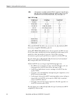
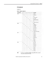
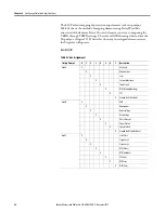
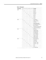
The 825-P allows mapping of protection (trip and warning) and general-purpose
control elements to the auxiliary outputs. Table 43 shows the method of mapping
the elements using Relay Word bits associated with the elements, except the
NETWORK, which is described below. Select 1 for each element you want to
map using the AUX# A through AUX# H settings. The relay will OR them
together to drive the Aux1 output.
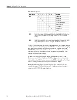
By default, the trip protection assignments are unlatched. The 825-P with
firmware revision 4.01 and higher can latch the trip protection assignment by
setting bit 4 in Aux #D. The user must reset the 825-P with the front Test/Reset
button or through communications to reset the auxiliary output.
If NETWORK is mapped to an AUX output, the DeviceNet network can
control the output. The DeviceNet can individually control those Auxiliary
outputs with NETWORK mapped to them.
Aux# H
X
Stopped State
X
Running State
X
Starting State
X
Star (Wye) Starting State
X
Delta Starting State
X
Start Command
X
Network Control
X
Reserved
NOTE:
The 825-P uses settings AUX# A through AUX# H and setting AUX# FAIL-SAFE in the output
logic (see Table 38 for more details) to determine the operation of the corresponding
auxiliary.
NOTE:
The AUX# A through AUX# D bytes are used to map trip functions to the output. The AUX# E
through AUX# H bytes are used to map warning and status functions to the output.
Table 43 - Aux Assignments
Setting Prompt
0
1
2
3
4
5
6
7
Description
Summary of Contents for 825-P
Page 1: ...Modular Protection System for Motors Catalog Number 825 P User Manual...
Page 4: ...4 Rockwell Automation Publication 825 UM004D EN P November...
Page 64: ...64 Rockwell Automation Publication825 UM004D EN P November 2012 Chapter 5 Using MPS Explorer...
Page 234: ...234 Rockwell Automation Publication 825 UM004D EN P April 2012 Chapter B ParameterList...
Page 265: ......

