7 — Connecting to data devices
7-10
2902 MainStreet Technical Practices
90-2906-01 May
2002
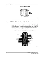
RJ45-to-DB25 adapter pin and signal assignment
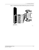
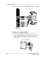
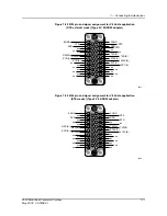
Figures 7-9 to 7-16 illustrate eight RJ45-to-DB25 adapter configurations. The
figures show the inside of a female adapter connector. Select the figure that matches
the adapter application (for example, straight-through CD), or the mode
configuration of your EIA/TIA-232 circuit and data device (for example,
synchronous DCE slave mode).
Use these figures as follows.
•
Pin 6 on the RS-232 personality module is the DTR lead at the 2902 MainStreet
system. The headshell wire is yellow if the adapter is a standard proprietary
user-configurable adapter.
•
The insertion pin on the yellow wire inserts into hole number 24 on the inside of
a female connector. The data device name for this lead is XCLK.
•
Adapter holes numbered 8, 20 and 6 are short circuited together with jumpers.
•
Headshell pin 7 (DSR) is spliced and goes to adapter pins 17 (SCR) and 15 (SCT).
Assembly notes
Figures 7-9 to 7-16 can also be used to determine pin and signal assignments for the
data equipment side of the adapter.
Note the following before you assemble an adapter.
•
If you have a standard proprietary user-configurable adapter, use the colors
indicated in the figure to identify the headshell wires.
•
If you do not have a standard proprietary user-configurable adapter, you must
determine and identify which headshell wires correspond to the EIA/TIA-232
personality module pins.
•
Each figure shows the inside of a female adapter connector; if you have a male
adapter connector, the location of the numbered adapter connector holes differs
from the figure. Use the hole numbers, not the hole locations, as your guide when
configuring a male adapter connector.
Summary of Contents for MainStreet 2902
Page 1: ...2902 MainStreet Network Termination Unit Release 1 0 H T E C H N I C A L P R A C T I C E S ...
Page 40: ...3 Mounting the unit 3 8 2902 MainStreet Technical Practices 90 2906 01 May 2002 ...
Page 50: ...4 Ground and power connections 4 10 2902 MainStreet Technical Practices 90 2906 01 May 2002 ...
Page 68: ...6 Connecting to the network 6 4 2902 MainStreet Technical Practices 90 2906 01 May 2002 ...
Page 90: ...7 Connecting to data devices 7 22 2902 MainStreet Technical Practices 90 2906 01 May 2002 ...
Page 108: ...10 Node management 10 10 2902 MainStreet Technical Practices 90 2906 01 May 2002 ...
Page 150: ...14 CPSS 14 6 2902 MainStreet Technical Practices 90 2906 01 May 2002 ...
Page 218: ...20 Codirectional DCM 20 6 2902 MainStreet Technical Practices 90 2906 01 May 2002 ...
Page 234: ...22 HCM rate adaption 22 10 2902 MainStreet Technical Practices 90 2906 01 May 2002 ...
Page 246: ...23 Cross connecting circuits 23 12 2902 MainStreet Technical Practices 90 2906 01 May 2002 ...
Page 254: ...24 Visual indicators 24 8 2902 MainStreet Technical Practices 90 2906 01 May 2002 ...
Page 266: ...25 Alarms 25 12 2902 MainStreet Technical Practices 90 2906 01 May 2002 ...
Page 278: ...26 System diagnostics 26 12 2902 MainStreet Technical Practices 90 2906 01 May 2002 ...
Page 298: ...27 Loopbacks 27 20 2902 MainStreet Technical Practices 90 2906 01 May 2002 ...
Page 332: ...Glossary GL 8 2902 MainStreet Technical Practices 90 2906 01 May 2002 ...
Page 343: ......
Page 344: ... 2002 Alcatel All rights reserved 90 2906 01 95 1820 01 00 C ...


