background image

27 —  Loopbacks

2902 MainStreet Technical Practices

27-7

May 2002  90-2906-01

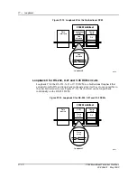
Figure 27-5  Loopback A for two-port DTUs

Loopback A for eight-port DTUs

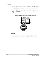
For eight-port DTUs, loopback A occurs on circuit A and circuit B simultaneously 

(see Figure 27-6). Loopback A extends from the DX on the Control card and loops 

back on the DNIC line driver located on the DNIC module.

Figure 27-6  Loopback A for eight-port DTUs

8850

DTU

DRAGA

2902 MainStreet

DNIC

module

Control

card

DX

DNIC

line driver

Loopback A

DNIC

line driver

8851

2902 MainStreet

DNIC

module

Control

card

DX

DNIC

line driver

DTU

DRAGA

Loopback A

Data

devices

1 to 8

DNIC

line driver

Summary of Contents for MainStreet 2902

Page 1: ...2902 MainStreet Network Termination Unit Release 1 0 H T E C H N I C A L P R A C T I C E S ...

Page 2: ... the use sale licence or other distribution of the products in such applications This document may contain information regarding the use and installation of non Alcatel products Please note that this information is provided as a courtesy to assist you While Alcatel tries to ensure that this information accurately reflects information provided by the supplier please refer to the materials provided ...

Page 3: ...uration provides the instructions on how to configure the node its modules and its connections Maintenance explains maintenance functions and how to perform them The glossary expands or defines acronyms and abbreviations The index lists entries for Installation Configuration and Maintenance Some systems do not include all the components or support all the features described in this documentation T...

Page 4: ...denoted by roman numerals and detail the actions involved in a complex step Complete each substep in order ii At least two substeps appear 2 This step has options a Options are denoted by letters and are conditional actions that depend on your system requirements Perform only the applicable option i Options may contain substeps ii At least two substeps appear b At least two options appear Danger D...

Page 5: ...906 01 Mandatory regulations The sections that follow outline the mandatory regulations governing the installation and operation of the 2902 MainStreet Network Termination Unit Adherence to these instructions is necessary to ensure regulatory compliance ...

Page 6: ...heat above 100 C 212 F or incinerate Warning 1 This unit contains no user serviceable parts Refer servicing to qualified personnel Warning 2 This equipment is Class I type and must be permanently earthed for protection and for functional purposes For safe operation and servicing the ac outlet must be installed near the equipment and must be readily accessible Use the appropriate ac power cord and ...

Page 7: ...om safety earth protective earth and EDG should be a minimum of 1 5 mm2 AWG 16 green and yellow in color and of sufficient length to connect the building earth point to the unit See section 4 1 for specific instructions Equipment interconnection points The interconnection points are defined as Safety Extra Low Voltage SELV all connectors on rear panel except P1 and P2 optical connectors Connect SE...

Page 8: ...it the cable diameter see Figure 1 Table 1 Ferrite beads for cables Figure 1 Ferrite beads and tie wraps on cables Product certification Commercial part number Cable diameter Steward 28A2025 0A2 5 08 to 6 35 mm Steward 28A2029 0A2 7 62 to 9 91 mm Steward 28A2024 0A2 9 53 to 12 70 mm 16521 Cable ties Connector Cable ties Ferrite bead Ferrite bead Connector Note Some products described in this manua...

Page 9: ...similar environment such that unauthorized user access is prevented Failure to prevent such user access will invalidate any approval given to this apparatus Power supply cord wiring The instructions for power supply cord and plug wiring are no longer mandatory If this information is required consult the Australian regulations section for details since both countries have identical power supply cor...

Page 10: ...ored markings identifying the terminals in the plug proceed as follows if power supply cord rewiring is required The core that is colored green and yellow must be connected to the terminal in the plug that is marked with the letter E or by the earth symbol or colored green and yellow The core that is colored blue must be connected to the terminal that is marked with the letter N or colored black T...

Page 11: ... Site selection 1 9 1 6 Installation summary 1 11 1 7 Installation tools and hardware required 1 11 2 Unpacking and inspecting the shipment 2 1 2 1 Antistatic precautions 2 2 2 2 Unpacking and inspecting the shipment 2 2 2 3 Performing a startup test 2 4 2 4 Repacking the shipment 2 4 3 Mounting the unit 3 1 3 1 Setting up the unit on a desk 3 2 3 2 Mounting the unit in a rack 3 2 3 3 Mounting the...

Page 12: ...ting to data devices 7 1 7 1 Data circuit connections 7 2 7 2 Assembling an adapter for EIA TIA 232 connections 7 9 7 3 DB25 to M34 cable pin and signal assignment 7 20 8 Connecting node management equipment 8 1 8 1 Node management equipment connections 8 2 9 Connecting to external alarm equipment 9 1 9 1 External alarm connections 9 2 10 Node management 10 1 10 1 Node management overview 10 2 10 ...

Page 13: ...nfiguration 13 12 14 CPSS 14 1 14 1 CPSS overview 14 2 14 2 CPSS channel connections 14 2 15 E1 module operating parameters 15 1 15 1 E1 module overview 15 2 15 2 Network connectors 15 3 15 3 E1 framing format 15 4 15 4 Signal earthing E1 G 703 LIM only 15 4 15 5 Master slave operation E1 HDSL and Optical LIMs only 15 6 15 6 Trunk conditioning 15 7 15 7 Fault classes 15 12 15 8 Alarm declaration a...

Page 14: ...9 2 19 2 X 21 and V 35 circuit operating parameters 19 2 19 3 Device mode 19 4 19 4 Device gender 19 4 19 5 Duplex method 19 5 19 6 RTS CTS delay 19 6 19 7 Control signals 19 7 19 8 Data structure asynchronous only 19 8 19 9 Clocking synchronous only 19 9 19 10 Multidrop data bridge 19 12 19 11 Super rate configuration for the X 21 and V 35 DCMs 19 13 20 Codirectional DCM 20 1 20 1 Understanding t...

Page 15: ...terface module LEDs 24 6 25 Alarms 25 1 25 1 Alarms and alarm queues 25 2 25 2 Viewing alarm queues 25 4 25 3 Acknowledging alarms 25 6 25 4 Deleting alarms 25 7 25 5 Reclassifying configurable alarms 25 7 25 6 Logging alarms 25 9 25 7 External alarms 25 10 26 System diagnostics 26 1 26 1 Diagnostic tests 26 2 26 2 Background diagnostics 26 3 26 3 Directed diagnostics 26 4 26 4 Viewing diagnostics...

Page 16: ... 29 1 29 1 Routing information 29 2 29 2 CPSS grooming 29 5 30 Database management 30 1 30 1 Backing up verifying and restoring the configuration database 30 2 30 2 Viewing and resetting the nonvolatile memory 30 5 31 Hardware maintenance procedures 31 1 31 1 Measuring the power rails 31 2 31 2 Testing and replacing the fuse 31 3 32 Primary rate link bypass 32 1 32 1 Initiating a primary rate link...

Page 17: ...y 2002 90 2906 01 1 Introduction 1 1 Product overview 1 2 1 2 Physical components 1 3 1 3 HDSL LIM overview 1 6 1 4 Optical LIM overview 1 8 1 5 Site selection 1 9 1 6 Installation summary 1 11 1 7 Installation tools and hardware required 1 11 ...

Page 18: ... HDSL and E1 Optical LIMs allow the 2902 MainStreet unit to serve as a high speed NTU providing low cost high speed X 21 or V 35 circuits for LAN interconnection E1 G 703 LIMs can also provide high speed connections to an E1 network Additionally an E1 G 703 LIM can be used as a tributary connection to a PBX allowing voice bypass connections to an E1 HDSL E1 Optical or another E1 G 703 LIM Figure 1...

Page 19: ...l card Figure 1 2 identifies the components for the unit Figure 1 2 2902 MainStreet unit interior rear view 9058 Power supply Protective earth Power switch Fuse holder Power receptacle Seven segment display Loopback LEDs Status LED EDG and Sig Gnd Slot 1 Slot 2 P1 Primary rate interface modules Data interface modules Control card position 1 Personality modules Line 1 Line 2 Modem Terminal Alarm Rx...

Page 20: ...nted inside the unit above the Control card It receives its power connection from the power connector module which contains an EMI filter fuse holder and power switch Control card The Control card is a multilayered printed circuit board that performs functions common to the entire system It contains the system software and configuration memory and supports up to two E1 primary rate LIMs and up to ...

Page 21: ...r each primary rate LIM on the Control card The jumpers are set to specify the termination impedance of each primary rate line 75 Ω or 120 Ω termination Data interface modules There are locations for two data interface modules on the Control card as shown in Figure 1 3 Physical position 1 on the Control card maps to logical position M01 on the NMTI while physical position 2 on the Control card map...

Page 22: ...et system can monitor external equipment for alarm conditions and can signal an alarm condition to an indicating device such as a light or buzzer LED indicators A Control card status LED a seven segment display and a group of four loopback LEDs are mounted on the edge of the Control card These provide information about card and module status and indicate activated loopbacks 1 3 HDSL LIM overview H...

Page 23: ...re 1 4 HDSL technology The Control card on a 2902 MainStreet system supports E1 HDSL LIMs in the same way that it supports E1 G 703 LIMs The E1 HDSL LIMs provide the same service as the E1 G 703 LIMs except that they use HDSL technology and do not provide the monitoring or bypass functions that are available on the E1 LIMs Figure 1 5 shows a typical application for E1 HDSL LIMs Figure 1 5 Typical ...

Page 24: ... by sending data in one direction at a time making the E1 Optical LIM immune to unwanted optical reflections This method allows a simplex single mode cable to be used in a full duplex application The E1 Optical LIM emulates an E1 G 703 LIM however the monitor and bypass modes on the E1 Optical LIM are not supported The E1 Optical LIM operates transparently with the node software and has the same c...

Page 25: ...that follow to ensure adequate access to equipment fault free operation personal safety Site requirements Install the unit in an area that meets the following general site requirements clean and dry well ventilated well illuminated Table 1 1 lists the specific site requirements 10451 PBX Video Data DNIC X 21 E1 G 703 LIM P2 E1 Optical LIM P1 2902 MainStreet NTU 15 km 9 mi Fiber cable Optical netwo...

Page 26: ... and the input voltage supplied Power consumption is 14 W for the Control card and approximately 4 W for each optional module See Table 1 2 for maximum power requirements Item Specification Power source Unswitched separate circuit providing one of the following ranges 90 to 110 V ac 100 V ac 6 10 207 to 253 V ac 230 V ac 10 Temperature Operating 0 to 40 C 32 to 104 F Shipping and storage 40 to 66 ...

Page 27: ...1 3 serves as a reference summary for the installation procedures Table 1 3 Installation summary 1 7 Installation tools and hardware required Table 1 4 lists the tools and hardware are required to install a 2902 MainStreet system listed by activity Some tools or hardware may not apply to your particular installation Supplied voltage Minimum voltage Maximum voltage Maximum power requirement 1 100 V...

Page 28: ...m your supplier part numbers 90 2367 01 and 90 2367 02 respectively Grounding Wire stripper Crimp tool One ring lug Three spade lugs Slot screwdriver 5 16 inch nut driver 10 12 or 16 AWG cable 2 6 2 0 or 1 5 mm nominal diameter Securing slide assembly cables Wire cutter Cable ties Installing modules 1 and 2 Phillips screwdrivers 2 nut driver Module extraction tool EPROM IC insertion tool EPROM IC ...

Page 29: ...nical Practices 2 1 May 2002 90 2906 01 2 Unpacking and inspecting the shipment 2 1 Antistatic precautions 2 2 2 2 Unpacking and inspecting the shipment 2 2 2 3 Performing a startup test 2 4 2 4 Repacking the shipment 2 4 ...

Page 30: ...rface such as a workbench or table Report any missing or damaged components to your account or technical support representative A part number label is shipped with each module The label shows the marketing part number an 8 digit number starting with 90 and manufacturing code suffix a single letter The label is designed to be affixed to the configuration record on the side of the chassis cover Figu...

Page 31: ...ic feet one ac power cord one documentation package Optional items are packed separately labeled for identification and include one or two LIMs one or two interface modules one or two personality modules one rack mount kit as applicable one rack mount slide assembly as applicable 3 Inspect the system and all the components carefully for obvious signs of damage 4 Check for a configuration record on...

Page 32: ...r mounting the 2902 MainStreet unit See section 4 4 for information on startup diagnostics Before connecting to an ac power source you must temporarily ground the unit by connecting the protective earth terminal chassis ground on the rear of the unit to the building ground 2 4 Repacking the shipment Repack the shipment in its original packing material Observe antistatic precautions If the original...

Page 33: ...2902 MainStreet Technical Practices 3 1 May 2002 90 2906 01 3 Mounting the unit 3 1 Setting up the unit on a desk 3 2 3 2 Mounting the unit in a rack 3 2 3 3 Mounting the unit in a slide assembly 3 3 ...

Page 34: ...ion 1 5 Procedure 3 1 To mount the unit in a rack Tools required 2 Phillips screwdriver one rack mount kit 19 inch available from your supplier part number 90 2901 01 1 Position the brackets and attach them to the unit with six 8 flathead screws supplied as shown in Figure 3 1 Figure 3 1 Attaching the brackets to the unit 2 Attach the shelf to the rack with the four panhead screws supplied as show...

Page 35: ...e 3 3 When shipped the slide bracket is installed in the shelf Before installing the unit you must remove the bracket from the shelf The general procedure to mount the unit in a slide assembly is as follows 1 Install the slide assembly in a rack 2 Attach the unit to the slide bracket 3 Install the slide bracket in the rack Figure 3 3 Slide assembly 8835 2902 MainStreet Network Termination Unit Pow...

Page 36: ...ure the slide assembly using the front set of brackets as shown in Figure 3 4 Figure 3 4 Installing the assembly with the front brackets b To install the unit so that it extends beyond the front of the rack attach the mid mount brackets to the rack mount assembly see Figure 3 5 Secure the assembly to the rack Figure 3 5 Installing the mid mount brackets 2 Loosen the thumbscrews grasp the front edg...

Page 37: ...unit to the slide bracket You need a 2 Phillips screwdriver to perform this task 1 Place the unit upside down on a flat surface and position the slide bracket upside down on top of the unit Align the front edge of the bracket with the front panel of the unit see Figure 3 7 2 Secure the slide bracket to the unit with four 8 32 screws supplied 8638 Tab Slide rails Slide Tab ...

Page 38: ...unit Procedure 3 4 To install the slide bracket in the rack 1 Fully extend the slide rails from the rack mount shelf 2 Align the slides on the slide bracket with the slide rails and push the bracket into the rails until the slides lock into place see Figure 3 8 8970 2 9 0 2 M a in S tr e e t Ne tw or k Te rm in at io n Un it ...

Page 39: ...ing service loops see section 4 3 for details Caution All cables must be properly connected and secured to avoid the risk of pinching the cables when the drawer is opened and closed Ensure that cables are secured before pushing the unit back into the rack 8969 Slide bracket Tab Slide rail 2902 MainStreet Network Termination Unit Power Event Status System Status Processor Out of Sync 1 Out of Sync ...

Page 40: ...3 Mounting the unit 3 8 2902 MainStreet Technical Practices 90 2906 01 May 2002 ...

Page 41: ...treet Technical Practices 4 1 May 2002 90 2906 01 4 Ground and power connections 4 1 Ground connections 4 2 4 2 Power connections 4 4 4 3 Securing slide assembly cable connections 4 4 4 4 Startup diagnostics 4 6 ...

Page 42: ...2902 MainStreet system The cables used for these ground connections must be long enough to reach the building ground point without splices The telecom safety earth cable should be 1 5 mm2 16 AWG and green and yellow in color Procedure 4 1 To ground the unit Tools required wire stripper crimp tool one ring lug three spade lugs slot screwdriver 5 16 inch nut driver 10 12 or 16 AWG wire 2 6 mm 2 mm a...

Page 43: ...ith the unit at a common point b For telecom safety earth attach a spade lug to the cable connect the cable to the Sig Gnd terminal and tighten the screw c For energy dumping ground attach a spade lug to the cable connect the cable to the EDG terminal and tighten the screw Figure 4 2 Ground connections Note If the unit is rack mounted in a slide assembly leave enough extra cable to form a service ...

Page 44: ...f the power cord into an unswitched ac outlet 4 Turn on the unit power switch The LEDs on the faceplate and rear panel run through their startup diagnostic patterns See section 4 4 for more information on startup diagnostics Figure 4 3 Connecting to ac power source 4 3 Securing slide assembly cable connections If the system is installed in a rack mount slide assembly you must ensure that the cable...

Page 45: ...s in a third loop Figure 4 4 Securing cables to the shelf with service loops top view 3 Wind the supplied plastic spiral wrap around the power and ground cables from their point of exit to the first cable tie fastening Trim any excess wrap with the wire cutters The wrap protects the cables from pinching when the unit is moved in and out of the assembly 4 Push the unit all the way into the shelf an...

Page 46: ... chapter 24 in Maintenance for descriptions of the visual indicators or if the indicators do not light in the pattern described Once the diagnostic tests have run successfully you are ready to initiate a node management session as described in chapter 10 in Configuration Figure 4 5 Front panel self test indicators Figure 4 6 Rear panel self test indicators Note Wait until the diagnostic tests are ...

Page 47: ... LED flashes with a 50 duty cycle 0 5 second on 0 5 second off Out of Sync 1 LED Out of Sync 2 LED Stay off for 1 second and then turn on After approximately 40 seconds these LEDs turn on again 1 Indicator Description Power indicator The power indicator for the Control card is the decimal point on the seven segment display The decimal point is lit when the Control card power is on Status LED The S...

Page 48: ...t the data has been received UART failure or communications failure 10 4 ms timer This test generates two 4 ms interrupts and verifies that the time between them is 4 ms Timer check failure 11 Data EDX memory This test writes and reads data from all data EDX chips to verify data integrity EDX test failure 12 Control DX memory This test writes and reads data from all Control card DX chips to verify...

Page 49: ...pback Framer 2 This test writes and reads data to the second E1 framer and verifies the data integrity E1 Framer failure 22 Thermometer This test writes and reads data from a register on the thermometer chip Thermometer not present or circuit malfunction 23 SEEP This test writes and reads data from the serial EPROM on the Control card SEEP test failure 24 125 µs timer This test generates a 125 µs ...

Page 50: ...4 Ground and power connections 4 10 2902 MainStreet Technical Practices 90 2906 01 May 2002 ...

Page 51: ...lling and removing modules 5 1 Control card modules 5 2 5 2 Opening the unit 5 2 5 3 Installing and removing primary rate modules 5 3 5 4 Installing and removing data interface modules 5 10 5 5 Installing and removing personality modules 5 11 5 6 Replacing EPROMs 5 12 ...

Page 52: ...s turned off and that the power cord is unplugged 2 Remove the seven top cover screws and slide off the top cover see Figure 5 2 If the unit has rack mount brackets attached remove them also 8839 LIM P1 Jumper blocks J37 J40 Jumper blocks J41 J44 LIM P2 EPROMs 3 4 1 2 Interface module position 2 Interface module position 1 Danger Hazardous voltages inside ensure that the power is off before removi...

Page 53: ...odules Procedure 5 2 To install E1 G 703 or E1 HDSL LIMs You need a 2 Phillips screwdriver to install E1 G 703 or E1 HDSL LIMs 1 Ensure that the unit is turned off and that the power cord is unplugged 2 Open the unit 3 Remove the screws from the appropriate Control card mounting posts 4 Locate the jumper blocks on the Control card corresponding to the module position Jumper blocks J37 and J40 corr...

Page 54: ... 75 Ω for the BNC connector variant and 120 Ω for the RJ45 connector variant For 75 Ω termination set the jumpers on the top and middle pins see Figure 5 4 For 120 Ω termination set the jumpers on the middle and bottom pins see Figure 5 4 b For E1 HDSL LIMs the jumpers must be configured for 120 Ω termination Set the jumpers on the middle and bottom pins see Figure 5 4 16567 75 J39 J40 J38 J37 120...

Page 55: ...pins for damage and try again if there is no damage Figure 5 5 Installing E1 G 703 or E1 HDSL LIMs 7 Screw the module to the mounting posts 8 Affix the module s label to the configuration record on the side of the unit Procedure 5 3 To remove E1 G 703 or E1 HDSL LIMs 1 Ensure that the unit is turned off and that the power cord is unplugged 2 Remove the screws that secure the module to its mounting...

Page 56: ... is not used for E1 Optical LIMs installed in the 2902 MainStreet system one extension bracket two 4 40 screws 3 8 in two 4 40 hex nuts two 4 flat washers two 6 32 screws 1 4 in 1 Ensure that the unit is turned off and that the power cord is unplugged 2 Open the unit 3 Remove the screws from the appropriate Control card mounting posts 4 Connect the fiber cable to the module see Figure 5 6 Do not o...

Page 57: ... and the two closest mounting posts and gently push down on the edge of the module nearest the female connector see Figure 5 7 Do not force a module into position you might bend the pins on the male connector If the module does not fit properly remove it examine the pins for damage and try again if there is no damage Figure 5 7 Installing the E1 Optical LIM 6 Screw the module to the mounting posts...

Page 58: ...oops until they have similar diameters and secure the loops by tightening the cable ties Do not overtighten Figure 5 9 Securing the fiber cable 9 Remove the screw from the Control card mounting post closest to EPROM 1 see Figure 5 10 10472 P1 Slot 2 Slot 1 Rx 1 P1 P2 Line 1 Line 2 Modem Terminal Alarm U 1 2 Display Status Loop Tx 1 Rx 2 Tx 2 O I EDG Sig Gnd Fiber cables E1 Optical LIMs P1 and P2 o...

Page 59: ... cord is unplugged 2 Remove the two screws that secure the module to the mounting posts on the Control card 3 Hold the module by the edges nearest to its connector and gently pull the module off the Control card Turn the module over and disconnect the fiber cable connector 5 Reinsert the screws into the posts 6 Remove the module s label from the configuration record 4 Warning To prevent damage to ...

Page 60: ... might bend or break when you push the module in all the way Figure 5 11 Installing a data interface module 2 Finish the installation by gently pushing down on the corners of the module Do not force a module into position you might bend the pins on the male connector If the module does not fit properly remove it examine the pins for damage and try again if there is no damage 3 Affix the part numbe...

Page 61: ...ey are used to secure the personality module 2 Hold the personality module by its edges insert it through the opening and align its connector with the male connector at the back of the mounting position Gently push the module part way into the male connector see Figure 5 12 Figure 5 12 Installing a personality module 3 Finish the installation by gently pushing the module all the way in Do not forc...

Page 62: ...are Before starting Verify that the system software upgrade kit contains the correct number of EPROMs The 2902 MainStreet unit Release 1 uses two EPROMS The EPROMs are labeled 80 2742 XX YY where XX identifies the variant number of the EPROM and YY identifies the revision number of the EPROM The number 2902 should appear on each label Note When you replace the EPROMs the current configuration sett...

Page 63: ...OM 1 with the IC insertion tool Align the dimpled side of the EPROM with the side of the socket marked with an arrow Carefully align the pins of the EPROM with the notches in the socket see Figure 5 14 Insert the EPROM Warning 1 Ensure that the power is off before inserting or removing EPROMs Warning 2 Always replace an old EPROM with a new EPROM having the same number using the correct socket War...

Page 64: ...Technical Practices 90 2906 01 May 2002 Figure 5 14 EPROM insertion 5 Repeat steps 3 and 4 for EPROM 2 part number 80 2742 02 YY 6 Place the old EPROMs in the packaging supplied with the new EPROM set Store the old EPROMs in a safe place 10449 Dimple Arrow ...

Page 65: ...2902 MainStreet Technical Practices 6 1 May 2002 90 2906 01 6 Connecting to the network 6 1 Primary rate connections 6 2 ...

Page 66: ...tors for twisted pair 120 Ω termination and the BNC connectors for coaxial cable 75 Ω termination Figure 6 1 Primary rate connectors Primary rate module pin and signal assignments Figures 6 2 and 6 3 identify the RJ45 connector pin and signal assignments for the 120 Ω E1 G 703 and E1 HDSL LIMs respectively Figure 6 4 identifies the BNC connector pin and signal assignments Figure 6 2 RJ45 network c...

Page 67: ...n section 4 3 Warning To avoid damage to the primary rate fiber cable s when installing other rear panel cables handle all cables carefully and ensure that the minimum bend radius for the fiber cable is 3 cm 1 25 in Note The 2902 MainStreet system is shipped with covering plates protecting optical connectors P1 and P2 Using a 2 Phillips screwdriver loosen the screws holding the covering plate s an...

Page 68: ...6 Connecting to the network 6 4 2902 MainStreet Technical Practices 90 2906 01 May 2002 ...

Page 69: ... Technical Practices 7 1 May 2002 90 2906 01 7 Connecting to data devices 7 1 Data circuit connections 7 2 7 2 Assembling an adapter for EIA TIA 232 connections 7 9 7 3 DB25 to M34 cable pin and signal assignment 7 20 ...

Page 70: ...one for each variant of the V 35 DCM Table 7 1 Interface and personality modules Notes 1 Personality module for V 35 internal and slave DCE modes 2 Personality module for V 35 external DCE and all DTE modes Note Personality modules are also known as interface adapters Interface module Personality module Type of connector RS 232 DCM 90 0611 01 RS 232 RJ45 90 1308 04 Dual RJ45 socket V 35 DCM 90 052...

Page 71: ... MainStreet series DTUs If a 2B1Q module is installed connect data devices via the 2700 MainStreet series DTUs Table 7 2 Data interface modules connectors and cabling Notes 1 There are two kinds of V 35 DB25 personality modules see Figures 7 3 or 7 4 2 Do not use 90 0360 01 cables with the unit as these cables do not support all the clocking modes 3 Only port 1 of the two RJ11 ports is used when a...

Page 72: ...ernal DCE and all DTE modes require the V 35 Type 2 interface adapter part number 90 1308 07 The signal names in Table 7 4 are the names at the 2902 MainStreet system connector If a proprietary DB25 to M34 cable is used the pin and signal assignments at the M34 end of the DB25 to M34 cable may be different See section 7 3 for pin and signal assignments Table 7 4 V 35 personality module pin and sig...

Page 73: ...ality module pin and signal assignment external DCE and all DTE modes 3 SCR B 4 DSR 5 CTS 6 nc 7 TXD B 8 nc 9 DTR 10 DCD 11 RTS 12 nc 13 nc 14 SCT A 15 RXD B 16 SCR A 17 nc 18 nc 19 nc 20 TXD A 21 nc 22 nc 23 nc 24 FGND 25 SGND Pin number Signal name if 2902 MainStreet circuit is DCE 2 of 2 V 35 type 2 8867 1 13 25 14 ...

Page 74: ...gnal assignments at the M34 end of the DB25 to M34 cable may be different See section 7 3 for pin and signal assignments Table 7 5 V 35 Type 2 personality module pin and signal assignment external DCE and DTE modes Pin number Signal name if 2902 MainStreet circuit is DCE Signal name if 2902 MainStreet circuit is DTE 1 SCT B nc 2 RXD A TXD A 3 SCR B XCLK B 4 DSR DTR 5 CTS ALB 6 XCLK A SCR A 7 TXD B...

Page 75: ...m connector The default mode is DCE If a 1 1 DB15 to DB15 cable is used the signal names will be the same at the cable end Table 7 6 X 21 personality module pin and signal assignment Pin number Configured as DCE Configured as DTE 1 Frame GND Frame GND 2 T A R A 3 C A I A 4 R A T A 5 I A C A 6 S A S A 7 nc nc 8 Signal GND Signal GND 9 T B R B 10 C B I B 11 R B T B 12 I B C B 13 S B S B 14 nc nc 15 ...

Page 76: ...or the other two pairs are reserved for future use The signal names are the names at the 2902 MainStreet system connector If a 1 1 RJ11 to RJ11 cable is used the signal names at the cable end will be the same Table 7 7 DNIC and 2B1Q personality module pin and signal assignment Figure 7 7 Codirectional G 703 personality module pin and signal assignment Note Only connector 1 can be used for connecti...

Page 77: ...devices use a 16 AWG common return ground to connect the telecom safety earth of each EIA TIA 232 device to the signal ground point on the rear panel 7 2 Assembling an adapter for EIA TIA 232 connections If you are connecting to EIA TIA 232 data equipment that has a DB25 port you need a 1 1 RJ45 to RJ45 cable and an RJ45 to DB25 adapter The adapter is either pre configured if purchased from us or ...

Page 78: ...onnector The data device name for this lead is XCLK Adapter holes numbered 8 20 and 6 are short circuited together with jumpers Headshell pin 7 DSR is spliced and goes to adapter pins 17 SCR and 15 SCT Assembly notes Figures 7 9 to 7 16 can also be used to determine pin and signal assignments for the data equipment side of the adapter Note the following before you assemble an adapter If you have a...

Page 79: ... 9 EIA TIA 232 sync DCE slave mode configuration 25 23 22 21 19 18 16 14 13 12 11 10 9 2937 24 20 17 15 8 7 6 5 4 1 2 3 XCLK SGND CTS SCR RTS RXD SCT TXD GND DCD DTR DSR 1 HOUT blue 2 HIN orange 3 RXD black 4 TXD red 5 SGD green 6 DTR yellow 7 DSR brown 8 FGD white Inside of female adapter connector ...

Page 80: ...0 EIA TIA 232 sync DCE external mode configuration 25 23 22 21 19 18 16 14 13 12 11 10 9 2940 24 20 17 15 8 7 6 5 4 1 2 3 SGND RXD TXD GND CTS RTS SCT SCR DCD DTR DSR 1 HOUT blue 2 HIN orange 3 RXD black 4 TXD red 5 SGD green 6 DTR yellow 7 DSR brown 8 FGD white Inside of female adapter connector XCLK ...

Page 81: ... slave mode configuration Note In Figure 7 11 for DTE slave mode SCT must be phase locked to SCR 25 23 22 21 19 18 16 15 14 13 12 11 10 9 9079 24 20 17 7 6 4 1 2 3 SGND RXD TXD GND DCD RTS XCLK SCR DTR DSR 1 HOUT blue 2 HIN orange 3 RXD black 4 TXD red 5 SGD green 6 DTR yellow 7 DSR brown 8 FGD white Inside of female adapter connector 5 8 ...

Page 82: ...ternal mode configuration Note In Figure 7 12 SCR and SCT must be frequency locked 25 23 22 21 19 18 13 12 11 10 9 8 5 16 2942 24 20 17 15 14 7 6 4 1 2 3 RXD TXD GND RTS SCR SCT DTR DSR SGND XCLK 1 HOUT blue 2 HIN orange 3 RXD black 4 TXD red 5 SGD green 6 DTR yellow 7 DSR brown 8 FGD white Inside of female adapter connector ...

Page 83: ... Straight through configuration EIA TIA 232 asynchronous in DCE mode 25 24 23 22 21 19 18 17 16 15 14 13 12 11 10 9 8 2943 20 7 6 5 4 1 2 3 DTR DSR SGND RXD TXD GND RTS CTS 1 HOUT blue 2 HIN orange 3 RXD black 4 TXD red 5 SGD green 6 DTR yellow 7 DSR brown 8 FGD white Inside of female adapter connector ...

Page 84: ... 14 Straight through CD configuration EIA TIA 232 asynchronous in DCE mode 25 24 23 22 21 19 18 17 16 15 14 13 12 11 10 9 2938 20 8 7 6 5 4 1 2 3 SGND RXD TXD GND DCD DTR DSR CTS RTS 1 HOUT blue 3 RXD black 4 TXD red 5 SGD green 6 DTR yellow 7 DSR brown 8 FGD white Inside of female adapter connector ...

Page 85: ... 15 Null modem configuration EIA TIA 232 asynchronous in DTE mode 25 24 23 22 21 19 18 17 16 15 14 13 12 11 10 9 8 2939 20 7 6 5 4 1 2 3 SGND RXD TXD GND DTR DSR CTS RTS Inside of female adapter connector 1 HOUT blue 2 HIN orange 3 RXD black 4 TXD red 5 SGD green 6 DTR yellow 7 DSR brown 8 FGD white ...

Page 86: ...nfiguration figure as a guide insert the pins of the headshell wires part way into the holes on the inside of the adapter connector see Figure 7 17 Splice and short circuit jumper connections as indicated in the configuration figure Figure 7 17 Inserting pins 25 24 23 22 21 19 18 17 16 15 14 13 12 11 10 9 5 2944 20 8 7 6 4 1 2 3 DTR DSR RXD TXD GND RTS DCD 1 HOUT blue 2 HIN orange 3 RXD black 4 TX...

Page 87: ...4 Cut the insertion pin off any unused lead and fold the wire into the adapter headshell see Figure 7 18 Figure 7 18 Folding in unused wires 5 Rotate the adapter connector 180 to facilitate closing the adapter see Figure 7 19 Figure 7 19 Rotating the adapter connector 6 Snap the adapter connector into the headshell see Figure 7 20 2950 2951 180o ...

Page 88: ...is cabling does not support all the system clocking modes The pin and signal assignments at the M34 end of the cable are given in Figures 7 21 to 7 23 pin and signal assignments at the personality module connector are given in Figures 7 3 and 7 4 Figure 7 21 M34 pin and signal assignment for V 35 data application DCE internal and slave modes 2952 E K P U Y S W AA C H B F R V T X D A J M N L Z BB C...

Page 89: ...des Type 2 V 35 DB25 adapter E K P U Y S W AA C H B F R V T X D A J M N L Z BB CC DD EE FF HH JJ KK LL MM NN 2945 CTS SGND PGND RTS nc DCD DSR DTR nc nc nc nc RXD B RXD A TXD A TXD B SCR B SCR A XCLK A XCLK B nc nc SCT A nc nc nc nc nc nc nc nc SCT B nc nc E K P U Y S W AA C H B F R V T X D A J M N L Z BB CC DD EE FF HH JJ KK LL MM NN 2946 nc SGND PGND RTS nc DCD DSR DTR nc nc nc nc RXD B RXD A TX...

Page 90: ...7 Connecting to data devices 7 22 2902 MainStreet Technical Practices 90 2906 01 May 2002 ...

Page 91: ...2902 MainStreet Technical Practices 8 1 May 2002 90 2906 01 8 Connecting node management equipment 8 1 Node management equipment connections 8 2 ...

Page 92: ...m connector through a modem The NMTI refers to Modem as serial port 2 The default setting for the Modem connector is DTE Once you have established a node management session you may change the serial port configuration for the 2902 MainStreet system For information on establishing a node management session see chapter 10 in Configuration Modem connector pin and signal assignment Figure 8 2 shows th...

Page 93: ... and Terminal connectors Tools and equipment required node management terminal such as a VT100 or compatible terminal a personal computer with VT100 terminal emulation software a personal computer with Craft Interface a computer running 5620 NM software cable RJ45 to RJ45 RJ45 adapters if necessary Adapters and cables can be obtained from your sales representative If your node management equipment...

Page 94: ...ction and Terminal for a direct connection 2 Connect the other end of the RJ45 cable to the modem or the node management terminal 3 Power up the node management terminal and ensure that its serial communication settings are compatible with the 2902 MainStreet system serial port default settings The serial port default settings for the 2902 MainStreet system are 1200 b s Modem 9600 b s Terminal 8 d...

Page 95: ...2902 MainStreet Technical Practices 9 1 May 2002 90 2906 01 9 Connecting to external alarm equipment 9 1 External alarm connections 9 2 ...

Page 96: ...y contacts of the external device The state of the Alarm In pins is configured through an NMTI session to detect normally open or normally closed contacts The opening or closing of the Alarm In pins causes the alarm External Alarm Raised to appear in an alarm queue The Event and Status relay contacts pins connect to the drive lines on the external devices The Event Status and the System Status rel...

Page 97: ... of closing or opening the relays Table 9 1 External alarm connector contact ratings Rating Resistive load Maximum operating voltage 60 V ac 60 V dc Maximum operating current 0 4 A 1 2 3 4 5 6 Alarm in Alarm in To system status alarm device To event status alarm device To system status alarm device To event status alarm device 8986 System status relay Event status relay 1 2 3 4 5 6 2902 MainStreet...

Page 98: ...11 cable with a distribution box connect the RJ11 connector to the box then connect the proper box terminals to the monitoring terminals of your device Procedure 9 2 To make connections for activating external alarm devices Tools required one RJ11 to spade lug cable or one RJ11 to RJ11 cable and a distribution box 1 Attach one end of the RJ11 cable to the Alarm connector 2 Attach the other end of ...

Page 99: ...tices 10 1 May 2002 90 2906 01 10 Node management 10 1 Node management overview 10 2 10 2 Logging in to the NMTI 10 2 10 3 NMTI screen display 10 4 10 4 NMTI main menus 10 6 10 5 Softkey menus 10 7 10 6 Logging out of the NMTI 10 9 ...

Page 100: ...lows you to initiate a node management session through a computer running the 5620 NM software The network manager and the 2902 MainStreet system communicate using the CPSS protocol which is a proprietary protocol similar to X 25 The network manager can connect directly to the 2902 MainStreet system It can also connect indirectly using a modem For information on using the 5620 NM for node manageme...

Page 101: ...ic 82211 ab cd Copyright 1996 1997 Alcatel All rights reserved where ab cd is the current software generic If the message does not appear check the connections and setup of the node management terminal 8 At the Enter level prompt type your access level number and press the key See section 11 5 for information on access levels If this is the initial session type 5 and press Level 5 users have read ...

Page 102: ...NMTI top level menu 10 3 NMTI screen display A sample NMTI screen is shown in Figure 10 2 The screen has five main areas header line data area command line diagnostics line softkey area 2902 MainStreet 82211 ab cd Alarms 6 No Date 8 47R 1 CONFIG 2 HOUSE 3 MAINT 4 STATS 5 ALARMS 6 7 8 9 QUIT 0 ...

Page 103: ... the 18 lines below the header line It displays information associated with the current menu for example configuration information or statistical reports Command line The command line is located directly below the data area It displays user input either the selected softkey or keyboard entries Header line Data area Command line Diagnostics line M01 Configured DNIC Installed DNIC Status OK Name Opt...

Page 104: ...ction key F1 to F10 or number key 1 to 9 and 0 10 4 NMTI main menus The top level menu displays the main menu titles in the softkey area of the screen To access a menu enter the relevant softkey either a function key or number key Configuration Configuration functions include programming a primary rate link configuring the circuits on the primary rate link configuring the interface modules definin...

Page 105: ...and significant events and displays alarms when they are generated Alarm functions include viewing and editing alarms logging alarms classifying alarms by priority configuring external alarm devices The menu functions are described in detail in the following chapters 10 5 Softkey menus For each menu function described in this manual a softkey menu is provided to show the path to the function Text ...

Page 106: ...ruction The system always prompts you to proceed when required Esc If the system is waiting for user input and you want to enter a softkey function press Esc and then the softkey For example to cancel or quit a function while the system is waiting for user input enter Esc 8 or Esc 9 If you enter only 8 or 9 the system assumes that it is part of the user input and will add the number to the command...

Page 107: ...ou are monitoring system alarms and want to update the information displayed you are examining the signaling leads a transmission error or some other event corrupts the displayed information 10 6 Logging out of the NMTI You can log out manually or to prevent unauthorized use of an unattended terminal you can program the length of time after which the NMTI automatically quits if there has been no a...

Page 108: ...10 Node management 10 10 2902 MainStreet Technical Practices 90 2906 01 May 2002 ...

Page 109: ...90 2906 01 11 Node parameters 11 1 System serial port parameters 11 2 11 2 Date and time 11 6 11 3 Node number and node name 11 7 11 4 Network Operations Center number 11 8 11 5 Access levels 11 9 11 6 Passwords 11 13 11 7 Viewing node parameters 11 14 ...

Page 110: ...ent equipment can be connected to a serial port a VT100 compatible terminal VT100 a printer PRINTER a computer VT100 CPSS CPSS_MODEM The default for serial port 1 is VT100 The default for serial port 2 is CPSS_MODEM Typically serial port 2 connects to a modem that connects to a 5620 NM or a PC running the Craft Interface Node Manager VT100 compatible terminal A VT100 compatible ASCII terminal can ...

Page 111: ...ode using the NMTI The node manager is sometimes referred to as the NOC A 5620 NM connected directly to a 2902 MainStreet system can back up verify and restore the configuration database connected indirectly via modem it can back up and verify but not restore For more details see chapter 30 in Maintenance communications software A PC running communications software can manage the node using the NM...

Page 112: ...00 b s 4800 b s 9600 b s The default for serial port 1 is 9600 b s for serial port 2 it is 1200 b s If you use the NMTI to back up verify or restore the configuration database to or from a separate computer one that is not managing the unit flow control is required for baud rates of 2400 b s or higher Flow control is discussed later in this section If you change a serial port baud rate the change ...

Page 113: ...ow control serial port 2 supports software and hardware flow control If you use the NMTI to back up verify or restore the configuration database to or from a separate computer one that is not managing the unit flow control is required for baud rates of 2400 b s or higher SER_PORT_1 SER_PORT_2 BAUD_RATE 9600 2400 4800 300 1200 600 HOUSE SK000467 Note Setting the flow control has no effect on serial...

Page 114: ...psed since the last system reset appears in the header line in the form hh mmR For example 4 03R indicates that 4 hours and 3 minutes have passed since the last system reset When the time is set real time appears in 12 hour format followed by the letter A or the letter P to indicate a m or p m respectively The format for entering the time is hh mmA or hh mmP Time can be entered in either 12 hour o...

Page 115: ...tenance for more information Node number The node number is the CPSS address used to uniquely identify your unit within a network managed by a proprietary network manager If the unit is part of a network managed by a non CPSS capable network manager the node number does not need to be set The node number can be any number from 1 to 999 inclusive When assigned it is displayed in the data area For a...

Page 116: ... The NOC number is displayed in the data area if the user has read only or read write access to the NOC_NUM softkey see Table 11 2 When setting the number include any prefix digits such as area code that would be required if the call were dialed manually from a telephone The number can include Hayes AT compatible modem dial modifiers such as a comma pause W wait for dial tone and wait for silence ...

Page 117: ...ements of the following types of user Table 11 2 lists suggested access level definitions Level 4 system manager The user is managing housekeeping functions related to user access and Control card non volatile memory maintenance functions Level 3 network configuration operator The user configures network interfaces signaling data processing applications system serial ports date and time Level 2 ne...

Page 118: ...RO RO RO RO R W R W R W R W R W R W R W R W HOUSE SER_PORT_1 SER_PORT_2 DATE TIME NODE_NAME MORE SESSN_TIME CHNG_PSSWD 2 NODE_NUM NOC_NUM RO RO RO RO RO RO n a RO RO RO RO R W R W RO RO n a RO RO R W R W R W R W RO RO n a RO RO R W R W R W R W R W R W n a R W R W MAINT DIAG UNDO_MAINT ON_CIRCUIT ON_MODULE MORE BACKUP RESTORE VERIFY VIEW_NET 3 NVM_DATA 3 RO RO RO RO RO RO RO n a n a R W R W R W R W...

Page 119: ... access the least restrictive definition the access definitions for POSITION CIRCUIT CONNECT and SYNCH are as defined Case 2 If CONFIG is defined as read only access more restrictive it overrides the definitions for POSITION and CIRCUIT Thus POSITION CIRCUIT and CONNECT have read only access and SYNCH has no access Case 3 If CONFIG is defined as no access the most restrictive it overrides the defi...

Page 120: ...Enter Default The display remains at the same softkey so that you can define the other levels 3 To define another softkey select CANCEL 4 To return to the main menu select QUIT 2902 MainStreet 82211 ab cd ELMSTREET Alarms 1 09 JAN 2002 8 40A CONFIG POSITION Level Access Type 1 Read Write 2 Read Write 3 Read Write 4 Read Write 5 Read Write CHANGE_ACCESS 1 LEVEL_1 2 LEVEL_2 3 LEVEL_3 4 LEVEL_4 5 6 7...

Page 121: ... Passwords must be between 8 and 12 alphanumeric characters long with no spaces When the system is first commissioned it is recommended that you change at least the level 5 password so that the node database is protected If you make a typing error while entering a password select Esc CANCEL the system returns to the previous menu Access level passwords are not saved as part of a configuration data...

Page 122: ...ure 11 2 shows the display Figure 11 2 Node parameter display LEVEL_1 LEVEL_2 LEVEL_4 LEVEL_3 new password new password PROCEED LEVEL_5 HOUSE MORE CHNG_PSSWD level5 password SK000473 2902 MainStreet 82211 ab cd NEWYORK Alarms 1 09 JAN 2002 8 46A Port Baud Rate Port Type Flow Control Level Zero Access 1 9600 VT100 NONE NO 2 1200 CPSS_MODEM NONE NO Current Port Serial port one Session Time 30 Minute...

Page 123: ...nd circuit configuration 12 1 Module position and circuit identifiers 12 2 12 2 Module position configuration 12 3 12 3 Module position displays 12 4 12 4 Naming a module position 12 8 12 5 Naming a circuit 12 8 12 6 Quick circuit configurations 12 8 12 7 Viewing circuit status 12 9 ...

Page 124: ...l module positions M02 to M08 and M10 to M16 are not user configurable because they are not physically present They are automatically reserved by the 2902 MainStreet system when a module capable of super rate speeds over 128 kb s that is an X 21 or V 35 DCM is configured in logical positions M01 or M09 see section 12 2 for more information Table 12 1 Module position and circuit identifiers Notes 1...

Page 125: ...igured you can reconfigure it as EMPTY After a module is installed and configured its status should be Ok If it is not make sure that the module is properly installed If there is still a problem check the alarm queue see chapter 25 in Maintenance Rather than configure each module position separately you can configure all positions for the modules currently installed The positions are configured au...

Page 126: ...n reserved module positions Empty module positions If logical module positions M01 or M09 are configured for a module that does not support super rate speeds over 128 kb s or as EMPTY the seven adjacent positions are automatically configured as EMPTY by the software Procedure 12 1 To configure an interface module position where pp is 1 or 9 Procedure 12 2 To configure all interface module position...

Page 127: ...lar to the SHOW_ALL display Table 12 2 describes the column headings and explains the status options The DSP module position is automatically configured to support super rate speeds because there are no user installable DSP resource modules currently available for the 2902 MainStreet system Figure 12 2 Sample module positions display single module position 2902 MainStreet 82211 ab cd Alarms 8 No D...

Page 128: ...SERVED Ok M15 EMPTY M08 RESERVED Ok M16 EMPTY P1 E1 E1 Ok P2 E1 E1 Ok DSP SUPERRATE SUPERRATE CONFIG POSITION Enter Module Position Number 1 TYPE 2 NAME 3 4 5 6 7 8 CANCEL 9 QUIT 0 Module Description The module position number Configured The type of module for which the position is configured Installed The type of module installed in that position Stat Empty no module is installed in the position ...

Page 129: ...ure 12 3 To view a single position CONFIG POSITION Pp or pp where p is 1 or 2 pp is 1 or 9 Procedure 12 4 To view a group of positions Procedure 12 5 To view all module positions To view all module positions enter CONFIG SHOW_ALL or CONFIG POSITION Esc SHOW_ALL Esc SHOW_1 8 Esc SHOW_9 16 CONFIG POSITION SK000485 ...

Page 130: ...T Pp c or pp c NAME circuit name where p c is a primary rate circuit p is 1 or 2 and c is 1 to 31 pp c is an interface circuit pp is 1 or 9 and c is 1 or 2 or A or B circuit name is a unique combination of up to eight alphanumeric characters with no spaces To delete a circuit name do not enter a name before pressing 12 6 Quick circuit configurations Rather than configure each circuit separately yo...

Page 131: ...transparent or HCM rate adaption Its exact use varies in each case Do not use this feature when configuring a multidrop data bridge To copy and adjust circuit information enter CONFIG CIRCUIT pp c COPY_ADJ pp c where pp c is an interface circuit pp is 1 or 9 and c is 1 or 2 or A or B 12 7 Viewing circuit status You can view the status of primary rate and interface circuits one at a time or in grou...

Page 132: ... module CONFIG CIRCUIT Pp c or pp c SHOW_GROUP SHOW_CCT where p c is a primary rate circuit p is 1 or 2 and c is 1 to 31 pp c is an interface circuit pp is 1 or 9 and c is 1 or 2 or A or B Default 2902 MainStreet 82211 ab cd Alarms 8 No Date 2 51R Circuit Name Type Function Fault Status P1 01 E1_DNIC DATA IDLE Configured CONFIG POSITION P1 1 1 SHOW_GROUP 2 NAME 3 COPY_TO 4 5 6 7 MORE 8 CANCEL 9 QU...

Page 133: ...ming and timing sources 13 1 System timing 13 2 13 2 Timing sources 13 3 13 3 Types of synchronization 13 6 13 4 Class number 13 7 13 5 Failure threshold 13 8 13 6 Recovery condition 13 9 13 7 Intra and inter sector links 13 10 13 8 Displaying the network configuration 13 12 ...

Page 134: ...n this case each node has access to all timing sources in the network This allows every node to receive timing signals from the same source ensuring network synchronization In addition ANS allows you to divide a network into sectors where each sector has independent timing Procedure 13 1 Standalone configuration summary 1 Enable standalone system timing on the node see Procedure 13 3 The STANDALON...

Page 135: ...onfigure them as intra sector links see section 13 7 These links carry timing and source routing information 5 Identify the CPSS links that are not used for ANS or the links that define sector boundaries and configure them as inter sector links see section 13 7 These links do not carry timing and source routing information Procedure 13 3 To set standalone or ANS system timing CONFIG SYNCH AUTO_SYN...

Page 136: ...eference the node selects the source that is the fewest number of hops away A hop is a link between two pieces of network equipment Current source failure When the current timing source is lost for example due to a node or a link failure the node switches to free run operation for approximately 10 seconds During this interval the node determines if there is an alternate path to the master source o...

Page 137: ...iled The system has unsuccessfully attempted timed recovery to the source The source has exceeded the permissible failure rate set under THRESHOLD The source was disabled by selecting DISABLE The source is in the default state The source was in the Cannot Lock state and an unsuccessful attempt to recover to the source was made Not Ready The source is not available for system timing Ready The sourc...

Page 138: ... its status changes from Current to Ready The system will then automatically select the Ready source with the highest preference lowest class number to be the new current source Procedure 13 4 To enable and select a source where source number is 1 or 2 13 3 Types of synchronization Each timing source can be set for the following type of synchronization internal FREE_RUN derived DERIVED If the curr...

Page 139: ...bers can be assigned to timing sources and to nodes When assigned to a node the class number refers to the internal clock of the node A class number of 15 indicates a source that does not normally supply network timing For example internal synchronization free run is assigned a class number of 15 so that it is the last source available Class numbers from 1 to 14 establish preferences among the pos...

Page 140: ...able or because of a node or link failure The threshold can be set between 0 and 30 or for no threshold unlimited If the number of source failures exceeds the threshold the source is disabled To make the source available again you must enable it as described in section 13 2 If the timing source recovers and the number of failures does not exceed the threshold the source is made available It will b...

Page 141: ... becomes available to the system enters the ready state as soon as it recovers The system attempts to synchronize to the recovered source if it has a lower class number than the current source Timed When timed recovery is selected the system continues to use the new current source but checks up to four times during the specified interval to see if the failed source has remained recovered If the so...

Page 142: ...he ANS option on CPSS links When the ANS option is enabled ANS timing and source routing information is included with the CPSS messages A CPSS link with ANS enabled is called an intra sector link this type of link is part of a sector A CPSS link with ANS disabled the default state is called an inter sector link this type of link provides a timing boundary between sectors Inter sector links can als...

Page 143: ...d position Attempting to define a second CPSS link for that position displays the message WARNING Pressing PROCEED will disable ANS for the position Selecting PROCEED makes the CPSS connection disables ANS for the position and removes the ANS softkey To access the ANS softkey again disconnect one of the CPSS connections If you select ANS when the synchronization is in standalone mode a message to ...

Page 144: ...uit number and the number of nodes in the network Figure 13 3 Network configuration display Procedure 13 11 To display the network configuration MAINT MORE VIEW_NET SHOW_NODES node number where node number is the node number from which to start between 1 and 1023 2902 MainStreet 82211 ab cd Alarms 1 No Date 0 000R Node 39 Clock Source Free Run Clock Cl 15 Nodes in Network 7 Node Hops Cl Circuit No...

Page 145: ...2902 MainStreet Technical Practices 14 1 May 2002 90 2906 01 14 CPSS 14 1 CPSS overview 14 2 14 2 CPSS channel connections 14 2 ...

Page 146: ... a proprietary network must dedicate at least one channel to CPSS The 2902 MainStreet unit supports a 16 kb s shared CPSS resource CPSS messages can be carried by timeslot 0 on E1 links a 64 kb s channel DS0 on all primary rate links the serial ports directly or through a modem 14 2 CPSS channel connections CPSS channel connections can be made using timeslot 0 a 64 kb s channel a serial port Times...

Page 147: ... is 1 to 30 CAS or 31 CCS pp c is the Codirectional DCM circuit number pp is 1 or 9 and c is 1 or 2 Procedure 14 3 To connect CPSS directly to the serial ports If the computer running the 5620 NM is plugged into a serial port make the following changes for CPSS communication Pp TS0 Pp TS0 CONFIG CONNECT SK000480 CPSS CPSS DISCONNECT TO_CIRCUIT TO_CIRCUIT DISC_FROM Pp c or pp c Pp c or pp c CONFIG ...

Page 148: ...management software Enter Procedure 14 4 To connect CPSS indirectly using the PSTN and modems If the computer running the 5620 NM is exchanging CPSS messages with the 2902 MainStreet system through modems and the PSTN make the following changes for CPSS communication Note The default data format for both serial ports is 8 data bits 1 stop bit no parity SER_PORT_1 300 9600 4800 2400 1200 600 SER_PO...

Page 149: ...ial port 1 Default for serial port 2 2 Set the device type for a modem Enter 3 Enter the phone number of the modem connected to the network manager computer HOUSE NOC_NUM phone number where phone number is the NOC number see section 11 4 for details SER_PORT_1 300 9600 4800 2400 1200 600 SER_PORT_2 BAUD_RATE HOUSE SK000482 SER_PORT_1 SER_PORT_2 PORT_TYPE HOUSE SK000674 CPSS_MODEM ...

Page 150: ...14 CPSS 14 6 2902 MainStreet Technical Practices 90 2906 01 May 2002 ...

Page 151: ...ule overview 15 2 15 2 Network connectors 15 3 15 3 E1 framing format 15 4 15 4 Signal earthing E1 G 703 LIM only 15 4 15 5 Master slave operation E1 HDSL and Optical LIMs only 15 6 15 6 Trunk conditioning 15 7 15 7 Fault classes 15 12 15 8 Alarm declaration and clearing times 15 13 15 9 E1 statistics 15 14 ...

Page 152: ...ffer as described in this chapter Figure 15 1 E1 G 703 LIM display Note 1 The system does not identify E1 G 703 LIM variants Ensure that you use the network connector that matches the impedance of the LIM Note 2 It takes approximately 60 seconds for master and slave HDSL LIMs to synchronize Synchronization is indicated on the front panel Out of Sync LEDs Note 3 Ensure that the jumpers for E1 G 703...

Page 153: ...tion according to ISO IEC 10173 TBR12 specifications The E1 G 703 LIMs can connect through BNC or RJ45 connectors The BNC connectors are the default selection for E1 G 703 LIMs The E1 HDSL LIMs can only connect through RJ45 connectors The E1 Optical LIM can only connect through FC_PC connectors and these network connectors are non configurable When RJ45 connectors are selected for an E1 G 703 LIM ...

Page 154: ...e transport of common channel signaling messages Timeslot 0 is used for framing The rest of the timeslots are labeled as in CAS Table 15 2 shows the timeslot to circuit relationships In Table 15 2 a timeslot is the ITU T specified channel designation of a primary rate channel and a circuit is the node management designation of a primary rate channel F stands for framing and S stands for signaling ...

Page 155: ...ard and through it to the telecom safety earth Normally both the receive and transmit lines are earthed Lines floating When a line is floating the earth side of the receive or transmit line is allowed to float because the differential between the line potential and the telecom safety earth is causing unusually high noise problems Procedure 15 3 To configure signal earthing for E1 G 703 LIMs If the...

Page 156: ...ainStreet node with software generic 82211 H0 00 or 82211 H0 01 you must use the BNC transmit shield option to program the LIM to be a master or slave By default the BNC shield option is set to TX_EARTH which corresponds to the master mode on an E1 HDSL LIM2 To program one of the E1 HDSL LIM2s for slave mode the BNC transmit shield option must be configured for floating For E1 HDSL LIM2s with soft...

Page 157: ...he trunk conditioning configuration for a primary rate interface can be changed at any time However any change disrupts service If any circuits on the link are cross connected when the trunk conditioning attributes are being changed the warning message WARNING Pressing PROCEED will result in a disruption of service is displayed on the diagnostics line The two types of trunk conditioning are two wa...

Page 158: ...en to idle first Information path On the information path of a primary rate circuit the system transmits all ones On the information path of a connected circuit the system transmits all ones if the circuit is a primary rate circuit if not it transmits all zeros Example If a primary rate circuit is connected to an X 21 circuit and a fault occurs on the primary rate link the information path is brok...

Page 159: ... Alarm Incoming AIS Framing FAS Err Rate Exceeded and Failed State the information path and the signaling path from the E1 primary rate circuit to the connected circuit are broken in the direction of the fault only If the connected circuit is a primary rate circuit the 2902 MainStreet system transmits seized idle or out of service fault signaling depending on the fault signaling selected for the c...

Page 160: ...unk conditioning breaks only the signaling path in the direction of the fault The information path is maintained in both directions If the connected circuit is a primary rate circuit the system transmits seized or idle fault signaling depending on the fault signaling selected for the connected circuit Unlike two way trunk conditioning if the fault signaling is seized the seized signaling code is t...

Page 161: ...receive path Procedure 15 5 To configure the type of trunk conditioning This enables trunk conditioning for all primary link faults where p is 1 or 2 Default You can select classes of alarms that cause trunk conditioning to be applied see section 15 7 Information path Signaling path Primary rate circuit 2902 MainStreet Connected circuit Signaling path Information path Direction of transmission Dir...

Page 162: ...for an alarm class no action is taken when an alarm in that class is raised Table 15 3 lists the four configurable fault classes Table 15 3 Fault classes and alarms Fault class Alarms Description Clearing Frame Framing Alarm Incoming AIS Multiframe Alarm Incoming TS16 AIS Includes alarms associated with frame alignment or multiframe alignment Cleared when frame alignment or multiframe alignment is...

Page 163: ...declaration time is useful when the primary rate link is subject to frequent short outages A shorter alarm declaration time is useful when an alternate path exists so that the length of time that service is disrupted is minimized The declaration time ranges from 0 1 to 30 seconds in 0 1 second increments the default is 0 8 second Alarm clear time The alarm clear time determines how long a fault mu...

Page 164: ...o 300 1 equals 0 1 second 15 9 E1 statistics You can configure the primary rate link to collect FAS or CRC4 statistics See chapter 28 in Maintenance for more information on E1 statistics Procedure 15 9 To configure the statistics type where p is 1 or 2 Default DECLARE n n CLEAR CONFIG POSITION Pp OPTIONS MORE ALARM_TIME SK000490 FAS_STATS CRC4_STATS CONFIG POSITION Pp OPTIONS SK000491 ...

Page 165: ...2902 MainStreet Technical Practices 16 1 May 2002 90 2906 01 16 E1 circuit operating parameters 16 1 E1 signaling type 16 2 16 2 E1 fault signaling 16 2 ...

Page 166: ...end signaling type For clear channel signaling a 64 kb s clear channel is created for which signaling is not passed Procedure 16 1 To configure E1 circuit signaling type where p is 1 or 2 and c is 1 to 31 Default 16 2 E1 fault signaling Fault signaling is the signaling code that the node applies to an interface when the interface to which it is cross connected is not available The options are seiz...

Page 167: ...es signal has meaning for the cross connected circuit Out of service type C signaling generates a yellow alarm on the DS1 circuit If fault signaling is turned off for any E1 circuit trunk conditioning is not applied to that circuit regardless of how it is configured for the link That is the circuit connected to the link stays connected during any red or yellow alarms Trunk conditioning is describe...

Page 168: ...16 E1 circuit operating parameters 16 4 2902 MainStreet Technical Practices 90 2906 01 May 2002 ...

Page 169: ...perating parameters 17 2 17 3 Device mode 17 3 17 4 Device gender 17 4 17 5 Duplex method 17 5 17 6 RTS CTS delay 17 5 17 7 Control signals 17 6 17 8 Data structure asynchronous only 17 7 17 9 Clocking synchronous only 17 9 17 10 Multidrop data bridge 17 12 17 11 Super rate configuration for DNIC or 2B1Q modules 17 13 17 12 Loss of synchronization debounce time DNIC only 17 14 ...

Page 170: ...9 17 2 DNIC and 2B1Q circuit configuration and operating parameters The circuits on a DNIC or 2B1Q module are numbered A and B The DNIC module connects to two port or eight port DTUs The 2B1Q module connects to two port DTUs When a module is used with a two port DTU circuit A communicates with DTU port A and circuit B communicates with DTU port B Each circuit that is DTU port can be configured ind...

Page 171: ...evice mode Data circuits support two device modes synchronous asynchronous Synchronous devices transmit a continuous stream of characters Synchronization between devices is maintained through timing signals that are transmitted on separate conductors Select synchronous if the data device connected to the module uses synchronous data communication When the circuit is configured as synchronous clock...

Page 172: ... device sends signals on the other wire For example the TXD signal means data is transmitted by a DTE and received by a DCE and the RXD signal means data is received by a DTE and transmitted by a DCE In general terminals and printers are DTE while modems are DCE However there are many exceptions If the owner s manual for the device indicates that the TXD signal is outgoing the device is DTE if it ...

Page 173: ...and c is A or B Default 17 6 RTS CTS delay RTS and CTS are control signals used to regulate data flow on half duplex lines When one device wants to send a message to a second device it sends an RTS After receiving the RTS the second device pauses and then returns a CTS The pause must be long enough to clear any messages that might be coming into the second device The pause is called the RTS CTS de...

Page 174: ...ured as high ON low OFF end to end END_TO_END End to end means the state of the local signal follows that of the signal source at the remote end of the network This option is only available when using HCM rate adaption Table 17 1 shows default control signal settings If the device is configured as synchronous DTR and DSR are not functional Table 17 1 DNIC and 2B1Q module control signal defaults No...

Page 175: ...s Selecting ON or OFF for inputs configures them as ASSUMED_ON or ASSUMED_OFF Selecting ON or OFF for outputs configures them as FORCED_ON or FORCED_OFF where pp is 1 or 9 and c is A or B 17 8 Data structure asynchronous only The data structure of asynchronous transmission has three configurable characteristics character length number of stop bits type of parity OUTPUTS DTR RI DSR DCD CTS RDL ALB ...

Page 176: ...asynchronous transmission The number of stop bits can be set to 1 bit default 2 bits Parity Parity is an error detection method that adds an extra bit to each transmitted character It is based on the number of zeros or ones in each character Five parity schemes are supported no parity default odd even mark space Procedure 17 7 To set the data structure where pp is 1 or 9 and c is A or B Default ST...

Page 177: ...nous transmissions are transmit clock source type of synchronous clocking Transmit clock source When the device mode is synchronous the clocking source between the DNIC or 2B1Q module and the attached data device is selectable The transmit clock can be supplied by the attached device EXTERNAL the data circuit to which the device is attached INTERNAL a remote source SLAVE default The way this param...

Page 178: ...le of a DTU clocking application Tables 17 3 and 17 4 provide some clocking combinations that describe their applications Table 17 3 DTU clocking applications DCE mode External The user equipment provides the transmit clock that is the XCLK pin from the DTE Slave The circuit extracts the transmit clock from the data stream DTE Internal external or slave These three options indicate the configurati...

Page 179: ...2902 MainStreet network DTU 1 is getting 2902 MainStreet network timing from the data network External Locked Slave Locked Yes Yes Used when the data network timing is locked to the 2902 MainStreet network timing Slave Independent Slave Independent Yes No Used when modems are providing the clocking independent of the 2902 MainStreet system clocking Modem or NTU DTU 2 DCE B A 2902 MainStreet networ...

Page 180: ... 2902 MainStreet unit in this type of application is in conjunction with a 3600 MainStreet Multiservice Bandwidth Manager containing a Sub Rate Interface module SRM Master and slave circuits must be configured with the same starting data position and transport bandwidth see chapters 21 and 22 To facilitate this the 2902 MainStreet system automatically sets the master circuit configuration to full ...

Page 181: ...ources on the Control card Super rate circuits on a DNIC or 2B1Q module are subject to the following limitations Super rate speeds can be configured for DTU port A port B or both However only one port may be cross connected at any one time If one port is configured for a super rate connection and you try to connect the other the system displays an error message If the circuit is already connected ...

Page 182: ...m x 8 kb s m is a multiplier Since the transport bandwidth for DNIC and 2B1Q modules is 64 kb s m 8 Procedure 17 12 To set the interface speed CONFIG CIRCUIT pp A FUNCTION RATE_ADAPT I F_SPEED 128 where pp is 1 or 9 17 12 Loss of synchronization debounce time DNIC only DNIC modules as well as 2600 MainStreet series DTUs use debounce timers to distinguish loss of synchronization from random line no...

Page 183: ...nge of debounce times for the CUSTOM option is 1 to 32767 ms 5 minutes 27 seconds in 10 ms increments Specify the debounce time in tens of ms from 1 to 32767 where for example 1 is 10 ms 2 is 20 ms 32767 is 327 670 ms Procedure 17 13 To set the debounce time where pp is 1 or 9 debounce_time is an integer between 1 and 32767 in 10 ms increments Figure 17 4 shows a sample debounce time configuration...

Page 184: ...ration display 2902 MainStreet 82211 ab cd Alarms 1 No Date 1 28R Configured Installed Status Name Options M01 DNIC Empty Empty Loss Of Sync Debounce DTU end 2000 ms Not Configurable Loss Of Sync Debounce Node end 250 ms CONFIG POSITION 1 OPTIONS SYNC_DEB NODE_LOSS 1 50_ms 2 3 1_sec 4 2_sec 5 CUSTOM 6 7 8 CANCEL 9 QUIT 0 ...

Page 185: ...e RS 232 DCM 18 2 18 2 RS 232 DCM circuit operating parameters 18 2 18 3 Device mode 18 3 18 4 Device gender 18 3 18 5 Full duplex 18 4 18 6 RTS CTS delay 18 4 18 7 Control signals 18 5 18 8 Data structure asynchronous only 18 6 18 9 Clocking synchronous only 18 7 18 10 Multidrop data bridge 18 9 ...

Page 186: ...ing characteristics of the data device connected to each circuit Procedure 18 1 To specify an RS 232 DCM CONFIG POSITION pp TYPE DATA RS 232 where pp is 1 or 9 18 2 RS 232 DCM circuit operating parameters Once you configure the module position the two circuits numbered 1 and 2 assume the default settings for each of the following operating parameters device mode device gender full duplex RTS CTS d...

Page 187: ...ured as asynchronous the data structure must be set see section 18 8 For more information on device mode see section 17 3 Procedure 18 2 To set the device mode where pp is 1 or 9 and c is 1 or 2 Default 18 4 Device gender The RS 232 DCM supports two device genders DTE DCE For more information on device gender see section 17 4 Note If asynchronous mode is selected transparent rate adaption cannot b...

Page 188: ...to half duplex 18 6 RTS CTS delay The RTS CTS delay regulates data flow on half duplex lines For more information see section 17 6 The range for RTS CTS delay is 0 to 140 ms in 10 ms increments Specify the delay in tens of ms from 0 to 14 where for example 0 is 0 ms 2 is 20 ms 14 is 140 ms The default is 0 ms The actual delay time may be up to 20 ms longer than the configured delay time For exampl...

Page 189: ... signaling is supported locally when CTS is configured END TO END RTS DCD end to end signaling is not supported DTR and DSR are not functional An RTS lead raised on the local end is propagated to the remote end as DCD The remote end must be able to extract the lead as DCD and pass it on to the user equipment RS 232 DCMs have limited control lead capability therefore they cannot extract and pass on...

Page 190: ...er length Character length is the number of data bits used to transmit a character in asynchronous transmission Character length can be set to 5 bits 6 bits 7 bits 8 bits default OUTPUTS DTR DSR DCD CTS RTS INPUTS END_TO_END ON OFF CONFIG CIRCUIT pp c FUNCTION CTRL_LEADS SK000504 Note A character must be 8 9 10 or 11 bits The number of bits in a character is the sum of the start bit always 1 chara...

Page 191: ...ata structure where pp is 1 or 9 and c is 1 or 2 Default 18 9 Clocking synchronous only Synchronous data devices require two clocking signals one for the receive data stream and one for the transmit data stream The receive clock supplies timing for receive data the transmit clock supplies timing for transmit data Transmit data and receive data are defined relative to the data device configured as ...

Page 192: ...tem LOCKED default to be passed through transparently INDEPNT Receive clock The receive clock on RS 232 DCMs with revision 2 DRAGA can be inverted The default is no inversion Receive clock inversion can compensate for a phase shift between the transmit clock and receive data signals if it occurs Transmit data Receive data DTE data device DCE data device Transmit clock Receive clock 1535 Clocking s...

Page 193: ...uld take turns communicating with a host computer The master device controls the use of the shared bandwidth by polling each slave in turn Figure 18 2 shows a multidrop data bridge Figure 18 2 Multidrop data bridge To create a multidrop bridge two components are needed a data interface that supports the multidrop function and a multidrop data bridge The 2902 MainStreet unit supports the multidrop ...

Page 194: ...signaling off These settings allow you to overlap the position of the data from these circuits For circuits in a multidrop data bridge if the circuit is configured as gender DCE the DCD control signal must be forced on If the circuit is configured as gender DTE the RTS control signal must be forced on Do not use the copy adjust function when configuring circuits that are to be part of the same mul...

Page 195: ...nd V 35 circuit operating parameters 19 2 19 3 Device mode 19 4 19 4 Device gender 19 4 19 5 Duplex method 19 5 19 6 RTS CTS delay 19 6 19 7 Control signals 19 7 19 8 Data structure asynchronous only 19 8 19 9 Clocking synchronous only 19 9 19 10 Multidrop data bridge 19 12 19 11 Super rate configuration for the X 21 and V 35 DCMs 19 13 ...

Page 196: ...scribed in section 19 11 Data devices connect directly to these DCMs eliminating the need for an external DTU You must configure a module position for an X 21 or V 35 DCM before you can configure the circuits of the module Procedure 19 1 To specify an X 21 or V 35 DCM where pp is 1 or 9 19 2 X 21 and V 35 circuit operating parameters Before implementing any of the procedures in this chapter you mu...

Page 197: ...is chapter describes the configuration of the parameters listed above Figure 19 1 Data circuit operating parameters Note Some of the procedures in this chapter use the FUNCTION softkey This softkey might not appear if the specified circuit is connected in which case you must disconnect the circuit before changing its function 2902 MainStreet 82211 ab cd Alarms 1 No Date 1 07P DATA CCT M01 01 NAME ...

Page 198: ...rcuit is configured as asynchronous the data structure must be set see section 19 8 For more information on device mode see section 17 3 Procedure 19 2 To set the device mode where pp is 1 or 9 and c is 1 Default 19 4 Device gender The circuit on the X 21 and V 35 DCMs supports two device genders DTE DCE For more information on device gender see section 17 4 Note If asynchronous mode is selected t...

Page 199: ...igured described in section 19 6 Full duplex transmission uses two independent transmission paths one in each direction allowing two connected devices to transmit and receive data simultaneously X 21 circuits The duplex method is not configurable for X 21 DCMs it is set to full duplex automatically V 35 circuits The duplex method is configurable except when a circuit is configured for a multidrop ...

Page 200: ...example 0 is 0 ms 2 is 20 ms 16 is 160 ms The default is 0 ms The actual RTS to CTS delay time may be up to 5 ms longer than the configured delay time For example by setting the RTS CTS delay time to 0 ms an actual delay of 0 to 5 ms could result This delay is in addition to any transmission delay which may be up to 500 ms for satellite links Procedure 19 5 To set the RTS CTS delay The RTS CTS sof...

Page 201: ...hen HCM rate adaption is used Table 19 1 shows the default control signals settings If the device is configured as synchronous DTR and DSR are not functional for V 35 DCMs Table 19 1 X 21 and V 35 DCM control signal defaults Note Control signals are the only interface parameter that can be set for a circuit that is configured as a timing source It is also the only interface parameter that can be c...

Page 202: ...a character in asynchronous transmission Character length can be set to 5 bits 6 bits 7 bits 8 bits default OUTPUTS DCD I C RTS ALB CTS INPUTS ON OFF END_TO_END CONFIG CIRCUIT pp c FUNCTION CTRL_LEADS SK000512 Note A character must be 8 9 10 or 11 bits The number of bits in a character is the sum of the start bit always 1 character length 5 6 7 or 8 stop bits 1 or 2 and parity bit 0 for no parity ...

Page 203: ...t the data structure where pp is 1 or 9 and c is 1 Default 19 9 Clocking synchronous only Synchronous data devices require two clocking signals one for the receive data stream and one for the transmit data stream The receive clock supplies timing for receive data the transmit clock supplies timing for transmit data Transmit data and receive data are defined relative to the data device configured a...

Page 204: ...pends on whether the circuit is in DCE or DTE mode Table 19 2 gives the transmit clock options for the DTE and DCE modes Table 19 2 X 21 and V 35 DCM clock sources Transmit data Receive data DTE data device DCE data device Transmit clock Receive clock 1535 Gender of circuit Clocking source Meaning X 21 circuit DCE and DTE Slave The circuit extracts the transmit clock from the data stream V 35 circ...

Page 205: ...more information ask your supplier representative for Configuration Note NCN305 entitled Data Interface Clocking Receive clock The receive clock on X 21 DCMs with revision 2 DRAGA can be inverted The default is no inversion Receive clock inversion can compensate for a phase shift between the transmit clock and receive data signals if it occurs If you are experiencing high bit error rates sometimes...

Page 206: ...dwidth Manager containing a Sub Rate Interface module SRM Master and slave circuits must be configured with the same starting data position and transport bandwidth see chapters 21 and 22 To facilitate this the 2902 MainStreet system automatically sets the master circuit configuration to full duplex and signaling off and the slave circuit configuration to half duplex and signaling off These setting...

Page 207: ...tection switching for super rate circuits is not supported Tandem super rate connections connections between two primary rate modules are not supported on the 2902 MainStreet system To make a super rate circuit connection cross connect an X 21 or V 35 DCM circuit with the master primary rate circuit the master circuit is the first of the contiguous channels on the primary rate link The slave circu...

Page 208: ... for a given transport bandwidth the number of primary rate channels used the multiplier and the number of reserved module positions For example for an interface speed of 400 kb s and a transport bandwidth of 40 kb s the multiplier is 10 Ten channels are used for the super rate circuit connection Restrictions If the interface speed is not a whole number multiple of the transport bandwidth the mess...

Page 209: ...36 280 224 168 64 128 512 448 384 320 256 192 72 144 576 504 432 360 288 216 80 160 640 560 480 400 320 240 88 176 704 616 528 440 352 264 96 192 768 672 576 480 384 288 104 208 832 728 624 520 416 312 112 224 896 784 672 560 448 336 120 240 960 840 720 600 480 360 128 256 1024 896 768 640 512 384 136 272 1088 952 816 680 544 408 144 288 1152 1008 864 720 576 432 152 304 1216 1064 912 760 608 456 ...

Page 210: ...the message Only 7 positions can be reserved If position M09 is reserved by position M01 position M09 cannot be configured Attempting to configure position M09 displays the message Cannot configure position reserved by M01 Attempting to reserve too few module positions displays the message Not enough reserved positions to support I F speed For example the transport bandwidth is 64 kb s the interfa...

Page 211: ... is reserved displays the message This logical position cannot be configured Procedure 19 10 To reserve module positions Module positions M01 and M09 can reserve seven module positions If module position M09 is configured as EMPTY module position M01 has the option of reserving 7 or 15 positions CONFIG POSITION pp OPTIONS NUM_RESERV n where pp is the module position either 1 or 9 n is the number o...

Page 212: ... 18 2902 MainStreet Technical Practices 90 2906 01 May 2002 Procedure 19 13 To set the interface speed CONFIG CIRCUIT pp c FUNCTION RATE_ADAPT I F_SPEED speed where pp is 1 or 9 and c is 1 speed is the interface speed in kb s ...

Page 213: ...90 2906 01 20 Codirectional DCM 20 1 Understanding the Codirectional DCM 20 2 20 2 Codirectional DCM Module and circuit parameters 20 2 20 3 Trunk conditioning 20 3 20 4 Alarm times 20 3 20 5 8 kHz timing 20 4 20 6 All Ones alarm indication signal 20 4 ...

Page 214: ...for the Codirectional DCM know the operating characteristics of the NTU to be connected to the circuit When you specify the module position the circuits on the module in that position assume the default settings and can be cross connected If you try to modify or cross connect circuits on a module position before it has been specified the display presents an error message Procedure 20 1 To specify ...

Page 215: ...ay trunk conditioning the path is broken in both directions This means that both the receive path and the transmit path will be broken If you change trunk conditioning operation is disrupted If you select two way trunk conditioning loss of input is raised for each input and must be cleared before circuits are reconnected Procedure 20 2 To configure trunk conditioning where pp is 1 or 9 Default 20 ...

Page 216: ...tional DCM circuit The two circuits on the Codirectional DCM can be set for 8 kHz timing upon circuit disconnection 8K_TIMING no 8 kHz timing upon circuit disconnection NO_8K default Procedure 20 4 To configure 8 kHz timing where pp is 1 or 9 and c is 1 or 2 Default 20 6 All Ones alarm indication signal An AIS All Ones alarm is raised whenever an all ones pattern is received on the input of a Codi...

Page 217: ...signal when a circuit is disconnected You can configure the Codirectional DCM so that it does not generate the all ones signal thereby preventing the far end from entering the AIS All Ones alarm condition Procedure 20 5 To configure AIS where pp is 1 or 9 and c is 1 or 2 Default AIS NO_AIS CONFIG CIRCUIT pp c FUNCTION TRUNK_COND SK000519 ...

Page 218: ...20 Codirectional DCM 20 6 2902 MainStreet Technical Practices 90 2906 01 May 2002 ...

Page 219: ...eet Technical Practices 21 1 May 2002 90 2906 01 21 Transparent rate adaption 21 1 Rate adaption overview 21 2 21 2 Transparent rate adaption overview 21 2 21 3 Transport bandwidth 21 3 21 4 Transport position 21 5 ...

Page 220: ...sents 1 bit and therefore 8000 b s of bandwidth Transparent rate adaption supports synchronous data running at a rate that is a multiple of 8 kb s If a device is transmitting asynchronous data transparent rate adaption cannot be used After transparent rate adaption is selected two parameters can be set transport bandwidth transport position Figure 21 1 shows how a transparent channel is represente...

Page 221: ...nnel how much of the DS0 is used and the interface speed data rate of the device The interface speed can be any multiple of 8 kb s up to 64 kb s but all speeds are not available to all DCMs Table 21 1 lists the interface speeds supported by the DNIC 2B1Q RS 232 DCM X 21 DCM and V 35 DCM 2902 MainStreet 82211 ab cd Alarms 1 No Date 0 01R DATA CCT M01 01 NAME B7 B6 B5 B4 B3 B2 B1 B0 Configured as SY...

Page 222: ...th is configured by entering an integer n that represents the number of 8 kb s elements n 1 to 8 The default is 64 kb s n 8 In Figure 21 2 example a shows the bandwidth allocation for a transparent channel with a transport bandwidth of 16 kb s n 2 example b shows 48 kb s n 6 with transport position changed to B5 Figure 21 2 Transport bandwidth examples transparent Module Interface speeds kb s DNIC...

Page 223: ...signing more than one subrate transparent channel to the same channel you must arrange the starting elements and the transport bandwidth so that the data from different devices do not overlap If you want to configure a number of circuits as a multidrop data bridge you must arrange the starting elements and the transport bandwidth to be the same See section 17 10 for DNIC and 2B1Q modules section 1...

Page 224: ...dth If there are not enough elements to the right of the transport position the transport bandwidth is automatically reduced to the available amount even if you have configured it for more To increase the transport bandwidth you may need to change the transport position first Procedure 21 3 To set the transport position where pp is 1 or 9 and c is 1 or 2 or A or B Bn is B7 to B0 TRANS_POS Bn CONFI...

Page 225: ...906 01 22 HCM rate adaption 22 1 Rate adaption overview 22 2 22 2 HCM rate adaption overview 22 2 22 3 Transport bandwidth 22 3 22 4 Transport position 22 5 22 5 Signaling and the signaling bit stream 22 5 22 6 Interface speed 22 6 22 7 Data position 22 8 ...

Page 226: ...erface speed data position Figure 22 1 shows an HCM frame displayed in an NMTI screen The HCM frame is a 10 row by 8 column matrix The rows are named F0 to F9 and columns are named B7 to B0 An element is identified by its row and column for example F3 B2 The F represents an element reserved for the framing bit which flags the start of the HCM frame A framing bit is needed because the HCM frame pat...

Page 227: ...e number of D elements available to the data device Unlike transparent rate adaption setting the transport bandwidth does not set the interface speed The interface speed is set separately see section 22 6 Note Some combinations of transport bandwidth transport position and data position parameters are incompatible The first D bit must be in one of the columns defined by the transport position and ...

Page 228: ...ome of the bit positions are not available for data Figure 22 2 shows an example of an HCM circuit with a transport bandwidth of 48 kb s n 6 and an interface speed of 9600 b s There are 6 columns and 12 D elements used Figure 22 2 Transport bandwidth example HCM Procedure 22 2 To set transport bandwidth CONFIG CIRCUIT pp c FUNCTION RATE_ADAPT TRANS_BW n where pp is 1 or 9 and c is 1 or 2 or A or B...

Page 229: ...t the transport position CONFIG CIRCUIT pp c FUNCTION RATE_ADAPT TRANS_POS Bn where pp is 1 or 9 and c is 1 or 2 or A or B Bn is B7 to B0 22 5 Signaling and the signaling bit stream The signaling parameter determines whether the data circuit in the HCM frame includes a signaling bit stream the S in Figure 22 2 Turning signaling off means that no bandwidth is taken up by signaling and that signalin...

Page 230: ...902 MainStreet Technical Practices 90 2906 01 May 2002 22 6 Interface speed The interface speed or data rate is the rate at which the device is transmitting data The speeds supported for HCM rate adaption are listed in Table 22 1 ...

Page 231: ...000 600 7200 600 4000 12 000 24 000 48 000 600 7200 600 4000 12 000 24 000 48 000 600 7200 600 4000 12 000 24 000 48 000 1200 38 400 1200 16 000 56 000 1200 9600 56 000 1200 9600 800 4800 14 400 28 800 56 000 1200 9600 800 4800 14 400 28 800 56 000 1200 9600 800 4800 14 400 28 800 56 000 2400 2400 19 200 2400 19 200 1800 14 400 1200 7200 16 000 32 800 57 600 1800 14 400 1200 7200 16 000 32 000 57 ...

Page 232: ...hree D bits Procedure 22 5 To set the interface speed where pp is 1 or 9 and c is 1 or 2 or A or B interface speed is in b s 22 7 Data position The data position parameter specifies the location of the first data element or D bit see Figure 22 1 When signaling is turned on the S bit appears in the element immediately before the first data bit signaling is turned on by default therefore the default...

Page 233: ...002 90 2906 01 Procedure 22 6 To set the data position where pp is 1 or 9 and c is 1 or 2 or A or B Ff Bn is the data position identifier Ff is the row number F0 to F9 and Bn is the column number B0 to B7 DATA_POSN Ff Bn CONFIG CIRCUIT pp c FUNCTION RATE_ADAPT SK000524 ...

Page 234: ...22 HCM rate adaption 22 10 2902 MainStreet Technical Practices 90 2906 01 May 2002 ...

Page 235: ...ross connecting circuits 23 1 Types of cross connections 23 2 23 2 Simple connections 23 2 23 3 Connecting super rate circuits 23 4 23 4 Circuit connections display 23 5 23 5 Protecting connections RAPID protection switching 23 5 23 6 Disconnecting connections 23 10 ...

Page 236: ...onnected a warning appears on the screen If you proceed the new connection is made and any existing connections involving the two original circuits are broken When connecting a primary rate circuit to an endpoint circuit the signaling types for both circuits must match If the primary rate circuit is configured with its default signaling type it automatically adopts the signaling type required by t...

Page 237: ...d for bypass operation by cross connecting circuits between the two primary rate modules Procedure 23 1 To cross connect simple circuits CONFIG CONNECT Pp c or pp c TO_CIRCUIT pp c or Pp c where p is 1 or 2 pp is 1 or 9 and c is 1 to 31 for primary rate or 1 2 A or B for interface module If the circuit is already connected a warning appears on the screen 2902 MainStreet Network Terminating Unit Po...

Page 238: ... cross connect super rate circuits CONFIG CONNECT pp c or Pp c TO_CIRCUIT Pp c or pp c where pp is 1 or 9 p is 1 or 2 and c is 1 to 30 for primary rate or 1 for X 21 or V 35 DCMs or A for DNIC or 2B1Q modules Note A super rate DNIC or 2B1Q connection cannot be made unless Port B of the DNIC or 2B1Q module is disconnected Message Reason for message Couldn t make connection insufficient bandwidth Th...

Page 239: ...gure 23 2 Circuit connections display 23 5 Protecting connections RAPID protection switching The 2902 MainStreet NTU provides RAPID circuit protection You can protect a connection by specifying an alternate connection in case of a circuit or link failure The original connection is called the preferred connection and the alternate connection is the protecting connection 2902 MainStreet 82211 ab cd ...

Page 240: ...ing connection Figure 23 3 Example of a protecting connection In general any two circuit types that can be used to form a preferred connection may also be used to form a protecting connection Exceptions are discussed later in this section Protection switching and fault signaling For protection switching that involves tandem nodes in an E1 environment the fault signaling for each inter node circuit...

Page 241: ...rcuits on link E1 1 are configured for seized or idle fault signaling at node 2 instead of OOS A or OOS B fault signaling node 3 is not informed that link E1 1 is down In this case node 3 does not switch the circuits on link E1 2 to their protecting circuits on link E1 4 Figure 23 4 Out of service signaling for tandem nodes Pointers for protecting circuits It is possible to share a protecting circ...

Page 242: ...nection between circuits 2 1 and P2 1 is overridden see Figure 23 6 Circuit 1 1 switches back to its preferred connection when circuit P1 1 becomes available Figure 23 5 Preferred connections available Caution A connection that shares a protecting circuit may be broken without warning at any time because the protecting circuit must connect to the circuit it has been configured to protect Primary r...

Page 243: ... to a link failure the protecting circuit also becomes unavailable For example in Figure 23 5 do not try to connect circuit 1 1 to circuit P1 1 and protect it by circuit P1 2 Procedure 23 4 To make a protecting connection 1 Make the preferred connection according to the simple cross connection instructions provided in section 23 2 Note Although the examples and illustrations in this section use pr...

Page 244: ... 1 PROT_BY P2 1 or CONFIG CONNECT P2 1 PROTECTING 1 1 23 6 Disconnecting connections To disconnect a connection specify one of the circuits If the connection is protected the softkeys PREFERRED and PROTECTION appear The preferred and protected connections are disconnected independently You can make disconnections one at a time or all at once PROTECTING pp c PROT_BY Pp c CONFIG CONNECT pp c or Pp c...

Page 245: ...23 7 To disconnect a super rate circuit A super rate circuit is disconnected by using its data module circuit identifier or its master circuit number If the primary rate circuit is not the master circuit the message Circuit is in the middle of a super rate group appears CONFIG CONNECT pp c or Pp c DISCONNECT where pp is 1 or 9 c is 1 for X 21 and V 35 DCMs or A for DNIC or 2B1Q modules p is 1 or 2...

Page 246: ...23 Cross connecting circuits 23 12 2902 MainStreet Technical Practices 90 2906 01 May 2002 ...

Page 247: ...2902 MainStreet Technical Practices 24 1 May 2002 90 2906 01 24 Visual indicators 24 1 LEDs 24 2 24 2 Front panel LEDs 24 2 24 3 Rear panel LEDs 24 4 24 4 Interface module LEDs 24 6 ...

Page 248: ...s System Status Out of Sync 1 and Out of Sync 2 as shown in Figure 24 1 Table 24 2 describes their normal operation and gives troubleshooting advice LED location LED name Color Front panel Power Processor Event Status System Status Out of Sync 1 Out of Sync 2 Green Green Yellow Red Red Red Rear panel mounted on the Control card Card Status Loopback four 1 Red Red V 35 and X 21 DCM Module Status Ci...

Page 249: ...ractices 24 3 May 2002 90 2906 01 Figure 24 1 Front panel LEDs 8831 Power Event Status System Status Processor Out of Sync 1 Out of Sync 2 2902 MainStreet Network Termination Unit Power Event Status System Status Processor Out of Sync 1 Out of Sync 2 ...

Page 250: ... If the Processor LED stops flashing check the alarm queues as described in section 25 2 Event Status 2 Not lit If the Event Status LED is lit there is an unacknowledged entry in the Major alarm queue Check the queue for the alarm See chapter 25 for more information on alarms System Status 2 Not lit If the System Status LED is lit there may be a problem with one or more of the following LIM E1 int...

Page 251: ...ber indicates the number of alarms 1 in the Major alarm queue If there are no flashing numbers and the decimal point is not lit ensure that the power switch is on verify that the power cord is firmly plugged in at both ends ensure that there is power at the outlet turn the power switch off and on Call your technical support representative for help if after performing the above actions there are st...

Page 252: ...ional DCMs have three LEDs as shown in Figure 24 3 The X 21 and V 35 DCMs and the DNIC and 2B1Q modules have two LEDs as shown in Figure 24 4 Table 24 4 describes their operation Figure 24 3 LEDs on the RS 232 DCM Figure 24 4 LEDs on the X 21 DCM 2830 Module status Circuit 1 status Circuit 2 status Module status Circuit status 5906 ...

Page 253: ...e If the LED is flashing the module is defective Replace the module Line status The line status LED monitors the line that runs from the module to the 2600 MainStreet series DTUs The LED is not lit if the module is not configured If the LED is lit the DNIC module is configured and synchronized with the DTU If it is not lit synchronization has been lost 2B1Q module Module status In normal operation...

Page 254: ...24 Visual indicators 24 8 2902 MainStreet Technical Practices 90 2906 01 May 2002 ...

Page 255: ...y 2002 90 2906 01 25 Alarms 25 1 Alarms and alarm queues 25 2 25 2 Viewing alarm queues 25 4 25 3 Acknowledging alarms 25 6 25 4 Deleting alarms 25 7 25 5 Reclassifying configurable alarms 25 7 25 6 Logging alarms 25 9 25 7 External alarms 25 10 ...

Page 256: ...e alarm as well as an alarm code The alarm code is a brief description of the nature of the alarm Some alarms codes have corresponding clearing codes which inform you that the alarm condition no longer exists Clearing codes are added to the appropriate alarm queue Clearing codes have names that are similar to their corresponding alarm codes but include terms such as cleared removed restored and no...

Page 257: ...out of service as a result The first parameter identifies the failed link Framing Err Rate Exceeded The E1 link error threshold was exceeded Framing AIS Red Alarms Frame alignment has been lost on an E1 link Check the first parameter of the subcode to identify the module then check the cable connections to the module and the E1 link HDLC Self Test Failed One of the HDLC presence or HDLC loopback s...

Page 258: ...Administration If you are reporting any problems to your representative make sure you include this alarm as it can help to identify a failure mechanism System Advisory SA This is a diagnostic software alarm related to System Administration If you are reporting any problems to your representative make sure you include this alarm as it can help to identify a failure mechanism Tail Circuit Gone The c...

Page 259: ...No Date 0 00R U 3 Framing Alarm P1 2 No Date 0 00R U 2 Module Inserted P1 11 0 0 1 No Date 0 00R U 1 Synch Source Changed 5 14 0 ALARMS MAJ PROMPT 1 ACK_All 2 3 DELETE_ALL 4 DELETE 5 ACK 6 7 8 CANCEL 9 QUIT 0 Column heading Description The queue number The item at the top of the list is the most recent alarm in the queue Use the alarm queue number when acknowledging or deleting an alarm Numbers ar...

Page 260: ...ges from U unacknowledged to A acknowledged and the alarm remains in the queue You can acknowledge a specific alarm or all alarms in a queue Code A brief description of the abnormal condition or significant event A complete list of alarm codes and detailed descriptions are included in Table 25 1 Each alarm code has a unique ID number Subcode and Parameters The alarm subcode and parameters if any S...

Page 261: ...is the number in the column of the alarm you wish to delete 25 5 Reclassifying configurable alarms Configurable alarms allow you to determine which queue the alarm is recorded in In the default configuration all configurable alarms are classified as Major Prompt You may want to configure alarms that need attention but are not an immediate threat to service as Minor Deferred or alarms that are advi...

Page 262: ...4 Framing AIS Red Alarms MAJ PROMPT 18 Power Rail Failed MAJ PROMPT 5 Distant Yellow Alarms MAJ PROMPT 19 Failed State MAJ PROMPT 6 External Alarm Raised MAJ PROMPT 20 Card Activity Change MAJ PROMPT 7 Synch Source Failure MAJ PROMPT 21 Busy Out Applied MAJ PROMPT 8 Wrong No Module Installed MAJ PROMPT 22 Signaling Fault MAJ PROMPT 9 Wrong Interface Card MAJ PROMPT 23 Module Reset MAJ PROMPT 10 De...

Page 263: ... the NOC over the PSTN and can serve as a backup method if the network CPSS link to the NOC fails This option is available only if one of the two serial ports typically serial port 1 has been configured to accept a modem see section 11 1 Local logging logs alarms to a local device such as a printer The serial port must be configured to accept a printer see section 11 1 Procedure 25 6 To log alarms...

Page 264: ...or information on connecting external alarm devices Monitoring a device To detect an external alarm the 2902 MainStreet system monitors its Alarm In pins for a change of state You can configure the external alarm function to assume the Alarm In contacts are normally open or closed The default setting is normally closed Activating a device If there is an unacknowledged alarm in the major alarm queu...

Page 265: ...25 Alarms 2902 MainStreet Technical Practices 25 11 May 2002 90 2906 01 Procedure 25 9 To set the external alarm function Default OPEN_CCT CLOSED_CCT ENABLE DISABLE ALARMS EXTNL_ALRM SK000534 ...

Page 266: ...25 Alarms 25 12 2902 MainStreet Technical Practices 90 2906 01 May 2002 ...

Page 267: ...Diagnostic tests 26 2 26 2 Background diagnostics 26 3 26 3 Directed diagnostics 26 4 26 4 Viewing diagnostics 26 5 26 5 Busy out circuits 26 6 26 6 Signaling leads 26 7 26 7 Displaying module and Control card maintenance information 26 10 26 8 Resetting a module or the Control card 26 10 ...

Page 268: ...ostics skip over circuits that are engaged Table 26 1 lists the diagnostic tests You can run all the tests in the background see section 26 2 or you can select a particular test see section 26 3 Table 26 1 Diagnostic tests Diagnostic test restrictions In order to run diagnostics or a particular test diagnostics must be enabled for the circuit the module s must be installed the test must be support...

Page 269: ...ackground diagnostics When system background diagnostics are enabled the system tracks any fault that occurs The system cycles continuously through the four diagnostics tests as listed in Table 26 1 If testing is disabled and re enabled it resumes where it stopped System background diagnostics are disabled by default and can be restarted from test 1 Circuit background diagnostics Circuit backgroun...

Page 270: ...gnostics disabled You can select a diagnostic test to run once X1 10 times X10 100 times X100 continuously or locked LOCK Directed diagnostics are supported for primary rate and interface module circuits If the specified circuit is busy the display shows the message Device momentarily unavailable for testing until the circuit is ready to be tested at which time the directed test is carried out Pro...

Page 271: ...stics You can view the diagnostic test currently being run SHOW_CUR a list of all the supported diagnostic tests SHOW_LIST the status of a circuit already tested that is whether it passed or failed the test FAULT_LIST Figure 26 1 shows a sample display where diagnostics have been enabled Note If the diagnostic test is number 4 you must enter a circuit number either pp c or Pp c after the LOCK X1 X...

Page 272: ...e you can perform maintenance functions such as loopbacks A circuit that is busied out is blocked from attempts by others to place it back in service or change any part of its configuration 2902 MainStreet 82211 ab cd Alarms 3 No Date 0 15R Diagnostic Test Number 2 Test No Function 1 Program Integrity 2 Ram Integrity 3 N V Ram Integrity 4 Digital Loopback Test MAINT DIAG 1 SHOW_CUR 2 SHOW_LIST 3 D...

Page 273: ...r what signal patterns are being sent out Outgoing signaling leads can be changed to force conditions at the far end For example it may be useful to cause a DTU to lose synchronization DNIC and 2B1Q signaling leads For DNIC and 2B1Q incoming signaling leads the Sync lead indicates whether or not the DTU is synchronized If the Sync lead is off the DTU is not synchronized and communication between t...

Page 274: ...eads Both the abbreviation and the digital representation of the signals are displayed with 0 indicating an off state and 1 indicating an on state The signaling leads display is not updated automatically To see the current states of the signaling leads at a given moment you must refresh the screen by pressing Esc R Procedure 26 8 To view signaling leads MAINT ON_CIRCUIT pp c SHOW_SIGNL CTRL_LEADS ...

Page 275: ...imes as you wish Any change you enter is temporary the signaling lead status is overridden if any normal network signaling is received Procedure 26 9 To change outgoing signaling leads where pp is 1 or 9 c is A or B signal is the signaling lead you wish to change signal state is 0 off or 1 on 2902 MainStreet 82211 ab cd Alarms 18 No Date 0 12R Circuit Type Loopback Status Connection M01 A DNIC Non...

Page 276: ...re 26 10 To view module information for maintenance purposes MAINT ON_MODULE pp or Pp or CTL where pp is 1 or 9 and p is 1 or 2 Figure 26 3 Module information display for maintenance 26 8 Resetting a module or the Control card If you have problems with a module for example if an alarm indicates that there is a module failure you may want to reset the module 2902 MainStreet 82211 ab cd Alarms 6 No ...

Page 277: ...em diagnostics 2902 MainStreet Technical Practices 26 11 May 2002 90 2906 01 Procedure 26 11 To reset a module or the Control card MAINT ON_MODULE pp or Pp or CTL RESET_POSN where pp is 1 or 9 and p is 1 or 2 ...

Page 278: ...26 System diagnostics 26 12 2902 MainStreet Technical Practices 90 2906 01 May 2002 ...

Page 279: ...1 May 2002 90 2906 01 27 Loopbacks 27 1 Using loopbacks 27 2 27 2 2B1Q circuit loopbacks 27 3 27 3 DNIC circuit loopbacks 27 6 27 4 Data circuit loopbacks 27 11 27 5 Primary rate circuit loopbacks 27 13 27 6 Primary rate link loopbacks 27 15 ...

Page 280: ...902 MainStreet system performs loopbacks on circuits primary rate and data and primary rate links Loopbacks on primary rate and data circuits can be unidirectional or bidirectional and can include loopbacks A B C or E Loopbacks on primary rate links include equipment and line loopbacks Bidirectional and unidirectional loopbacks Loopbacks are either bidirectional unidirectional or unidirectional wi...

Page 281: ...Primary rate loopback LEDs on the Control card see section 24 3 indicate that the 2902 MainStreet system is running a primary rate loopback When a loopback is in progress for a circuit the circuit status has M for maintenance appended to it Procedure 27 1 To remove a specific loopback MAINT ON_CIRCUIT pp c or Pp c UNDO_MAINT where pp is 1 or 9 c is 1 2 A or B p is 1 or 2 c is 1 to 31 Procedure 27 ...

Page 282: ...d in super rate connection Loopback A Figure 27 2 shows loopback A which occurs simultaneously on both circuits DTU ports A and B Loopback A extends from the DX on the Control card and loops back on the 2B1Q line driver located on the 2B1Q module Figure 27 2 Loopback A for 2700 MainStreet series DTUs Loopback B Figure 27 3 shows loopback B which is a bidirectional loopback that can be initiated on...

Page 283: ...ped back within the DTU in the DRAGA chip at the end nearest the data device The signal from the data device is also looped back in the DRAGA at the end nearest the data device Figure 27 4 Loopback E for 2700 MainStreet series DTUs 2902 MainStreet 2B1Q module Control card DX 2B1Q line driver DTU DRAGA Loopback B Data device 16581 DRAGA 2902 MainStreet 2B1Q module Control card DX 2B1Q line driver D...

Page 284: ...ile neither is connected the system displays the following error message Connect super rate circuit before applying loopbacks If a loopback is applied to one port while the other is involved in a super rate connection the system displays the following error message Loopback invalid other port involved in super rate connection Loopback A for two port DTUs For two port DTUs loopback A occurs on both...

Page 285: ...ultaneously see Figure 27 6 Loopback A extends from the DX on the Control card and loops back on the DNIC line driver located on the DNIC module Figure 27 6 Loopback A for eight port DTUs 8850 DTU DRAGA 2902 MainStreet DNIC module Control card DX DNIC line driver Loopback A DNIC line driver 8851 2902 MainStreet DNIC module Control card DX DNIC line driver DTU DRAGA Loopback A Data devices 1 to 8 D...

Page 286: ...looped back in the DRAGA chip also but on the inside of the DRAGA Figure 27 7 Loopback B for two port DTUs Loopback B for eight port DTUs For eight port DTUs loopback B is a bidirectional loopback that can be initiated from either circuit A or B see Figure 27 8 The signal from the Control card is looped back within the DTU inside the DRAGA chip The signals from the data devices connected to the se...

Page 287: ...ed back within the DTU inside the DRAGA chip see Figure 27 9 The signal from the data device is looped back in the DTU at the DRAGA on the side closest to the data device Figure 27 9 Loopback C for two port DTUs 8962 2902 MainStreet DNIC module Control card DX DNIC line driver 2606 MainStreet DTU DRAGA Loopback B Data devices 1 to 8 DRAGA 8853 2902 MainStreet DNIC module Control card DX DNIC line ...

Page 288: ...in the DTU inside the DRAGA chip The signals from the data devices connected to the selected aggregate port are looped back on the side closest to the data devices Figure 27 10 Loopback C for eight port DTUs Procedure 27 4 To set a DNIC circuit loopback where pp is 1 or 9 and c is A or B 8854 2902 MainStreet DNIC module Control card DX DNIC line driver DTU DRAGA Loopback C Data devices 1 to 8 DRAG...

Page 289: ...gure 27 11 Loopback B for RS 232 X 21 and V 35 DCMs Loopback B Codirectional DCM circuits Loopback B for the Codirectional DCM occurs at the tributary output see Figure 27 12 While Loopback B is applied to a Codirectional DCM circuit 8 kHz timing is turned on and all ones is turned off Even if the Codirectional DCM circuit has been configured not to generate 8 kHz timing it generates 8 kHz timing ...

Page 290: ... that extends from the DX and loops back in the gate array itself as close as possible to the attached data device see Figure 27 13 Each circuit can be looped back individually on the RS 232 DCM Figure 27 13 Loopback C for RS 232 X 21 and V 35 DCMs Data interface 2902 MainStreet Codirectional DCM Control card DX Line interface Loopback B 8856 Line interface Data device 2902 MainStreet DCM Control ...

Page 291: ...ectional DCM Procedure 27 5 To set a DCM circuit loopback where pp is 1 or 9 and c is 1 or 2 27 5 Primary rate circuit loopbacks The 2902 MainStreet system supports two types of primary rate circuit loopbacks Loopback A and Loopback C Both types can be performed on a LIM at the same time Data interface 2902 MainStreet Codirectional DCM Control card DX Line interface Loopback C 8858 DX UNDO_MAINT O...

Page 292: ...on the E1 framer and is passed through to the far end Figure 27 15 Loopback A for primary rate circuits Loopback C Loopback C is a bidirectional loopback Figure 27 16 shows Loopback C The signal from the system is looped back in the DX on the Control card The signal from the primary rate circuitry is looped back at the side of the Control card closest to the primary rate circuitry DX E1 Framer 290...

Page 293: ...st end to end connections over a primary rate link When initiated the entire link is looped back DX E1 Framer 2902 MainStreet Control card E1 G 703 HDSL or Optical LIM 9115 DX UNDO_MAINT ON_CIRCUIT Pp c LOOPBACK_A LOOPBACK_C UNDO_LPK MAINT SK000544 Caution Initiating a primary rate link loopback causes all calls in progress on the selected module to be dropped No new calls can be initiated on the ...

Page 294: ... See section 24 3 Figure 27 17 Equipment loopback for E1 G 703 and E1 Optical LIMs HDSL LIMs When an E1 HDSL LIM is configured for an equipment loopback the signal is looped back toward the node and passed through to the far end as shown in Figure 27 18 The loopback occurs as close to the HDSL output as possible Note It can take up to 60 seconds to establish an HDSL or optical link loopback 9116 2...

Page 295: ...be initiated on both primary rate links at the same time E1 G 703 and E1 Optical LIMs Figure 27 19 illustrates the line loopback for the E1 G 703 and E1 Optical LIMs The signal originates from the E1 link is looped back at the E1 LIM and passes through to the DX on the Control card Control card 2902 MainStreet HDSL LIM or HDSL LIM2 11867 HDSL pair 1 MUX Loop 1 interface Loop 2 interface HDSL pair ...

Page 296: ...ignal received from the HDSL line back to the network and passes it through to the Control card see Figure 27 20 Figure 27 20 Line loopback for E1 HDSL LIMs 8863 2902 MainStreet Primary rate interface Control card DX DX LIM Primary rate line loopback DX LIM Control card 2902 MainStreet HDSL LIM or HDSL LIM2 11869 HDSL pair 1 MUX Loop 1 interface Loop 2 interface HDSL pair 2 ...

Page 297: ...ices 27 19 May 2002 90 2906 01 Procedure 27 7 To initiate a primary rate loopback where p is 1 or 2 Procedure 27 8 To remove a primary rate loopback MAINT ON_MODULE Pp UNDO_LPK where p is 1 or 2 LINE EQUIPMENT MAINT ON_MODULE Pp LOOPBACK SK000546 ...

Page 298: ...27 Loopbacks 27 20 2902 MainStreet Technical Practices 90 2906 01 May 2002 ...

Page 299: ...2902 MainStreet Technical Practices 28 1 May 2002 90 2906 01 28 Statistics 28 1 Synchronization statistics 28 2 28 2 FAS and CRC4 statistics 28 3 28 3 Codirectional DCM quality statistics 28 7 ...

Page 300: ...formation on synchronization sources see section 13 2 in Configuration Procedure 28 1 To display synchronization statistics STATS SYNCH A screen display similar to Figure 28 1 appears Table 28 1 describes the fields on the display Figure 28 1 Synchronization statistics display 2902 MainStreet 82211 ab cd Alarms 6 No Date 3 01R System Synch Connect Time Current Synch Source Free Run Curr Interval L...

Page 301: ...tistics are updated every 15 minutes to reflect the previous 24 hour period and can be cleared automatically or manually Item Description Current Interval The number of seconds the source has been in use during the current 15 minute interval you can update the information by refreshing the screen Esc R Last Hour The number of seconds the source was in use for the last hour The listing does not inc...

Page 302: ...rvice time remote out of service time total slip count FAS and CRC4 statistics can either be cleared manually or cleared automatically every 24 hours at midnight the error event count is not cleared automatically Procedure 28 4 To configure the statistics type The type of statistics collected FAS or CRC4 is selected when you configure the module position where p is 1 or 2 Default Procedure 28 5 To...

Page 303: ...pe E1 FAS Status Red Alarm Current Interval Accumulated Worst Interval 456 sec 168 2 00P Available Time 191 7310 900 Local Out of Service Time 5 976 27 Remote Out of Service Time 0 0 0 Total Slip Count 64 298 37 Errored Seconds 0 0 N A Severely Errored Seconds 0 0 0 Failed Seconds 0 0 0 Error Events since last clear 0 STATS QUALITY P1 1 CLR_STATS 2 CLR_ERR_EV 3 4 5 6 7 8 CANCEL 9 QUIT 0 ...

Page 304: ...mulated statistics since the last time the statistics were cleared The statistics are automatically cleared reset to 0 every 24 hour period at midnight if automatic clearing is selected otherwise they must be cleared manually Worst Interval For the categories Available Time Local Out of Service Time Remote Out of Service Time and Total Slip Count this column lists the statistics for the interval i...

Page 305: ...t is cleared without clearing any other FAS or CRC4 statistics STATS QUALITY Pp CLR_ERR_EV where p is 1 or 2 28 3 Codirectional DCM quality statistics Quality statistics for the Codirectional DCM display the slip count see Figure 28 3 A slip indicates that a byte has been inserted or deleted at the receiver the line rate is too slow insert or too fast delete relative to the system timing Slips are...

Page 306: ...lity statistics STATS QUALITY pp where pp is 1 or 9 Procedure 28 10 To clear Codirectional DCM quality statistics STATS QUALITY pp CLR_STATS where pp is 1 or 9 2902 MainStreet 82311 ab cd Alarms 1 No Date 3 50P Link Quality Position M01 Type 64K_CODIR Status Module Present CIRCUIT 1 Slip Count 14 CIRCUIT 2 Slip Count 35 STATS QUALITY P1 1 CLR_STATS 2 3 4 5 6 7 8 CANCEL 9 QUIT 0 ...

Page 307: ...2902 MainStreet Technical Practices 29 1 May 2002 90 2906 01 29 CPSS maintenance 29 1 Routing information 29 2 29 2 CPSS grooming 29 5 ...

Page 308: ... show different routing information all nodes in the network SHOW_NODES all nodes in the network that are a specified number of hops CPSS links away from the 2902 MainStreet system HOPS_AWAY all nodes in the network that use a specific path to communicate with the 2902 MainStreet system VIA_PATH In each case you specify a node number The display lists all nodes having a node number equal to or gre...

Page 309: ...e node number is the node number from which to start searching for routing table information Figure 29 2 illustrates a sample network and Figure 29 3 illustrates a SHOW_NODES display where the node number entered is 3 Table 29 1 describes the column headings in the display The top line of the data area shows the node number of the node you are logged on to its current clock source and class and th...

Page 310: ...1 ab cd Alarms 1 No Date 0 00R Node 39 Clock Source Free Run Clock Cl 15 Nodes in Network 7 Node Hops Cl Circuit Node Hops Cl Circuit Node Hops Cl Circuit 14 1 0 P1 01 52 2 0 P1 P1 78 3 0 P1 01 26 1 0 P2 17 65 2 0 P1 01 1023 2 0 P1 01 MAINT VIEW_NET SHOW_NODES 3 1 2 3 4 5 6 7 8 CANCEL 9 QUIT 0 Column heading Description Node Indicates the node number Hops Indicates the node distance in hops from t...

Page 311: ...A display similar to Figure 29 3 appears It shows information on the nodes to which the 2902 MainStreet system can send CPSS messages via the specified path 29 2 CPSS grooming In a network made up of Alcatel proprietary equipment only one channel per pair of adjacent nodes needs to be dedicated to CPSS messages However if Alcatel proprietary equipment is connected to a network made up of third par...

Page 312: ...on the left of the 2902 MainStreet node the 2902 MainStreet node connects the single CPSS channel to the DS0 for node 3 for the message to pass On the right hand side of the 2902 MainStreet node each CPSS channel is routed separately and transparently through the third party network from the 2902 MainStreet node doing CPSS grooming to the other proprietary equipment Note Timeslot 0 and all 30 DS0s...

Page 313: ... MainStreet Technical Practices 30 1 May 2002 90 2906 01 30 Database management 30 1 Backing up verifying and restoring the configuration database 30 2 30 2 Viewing and resetting the nonvolatile memory 30 5 ...

Page 314: ...dy to receive the data transfer For example a PC must be running software that captures incoming serial data to be stored in an ASCII file The device must be connected to a properly configured 2902 MainStreet system serial port For baud rates of 2400 4800 and 9600 b s the flow control must be set The backup procedure can last several minutes depending on the selected baud rate and the complexity o...

Page 315: ...urs the system reloads the factory set default configuration The default database does not contain any user configurations such as cross connections or module parameter settings When the configuration database is restored the node name and number are maintained from the previous configuration passwords and session time return to their defaults and access levels are restored from the backup file Th...

Page 316: ...to XON XOFF or DTR DTR flow control is supported on serial port 2 only If the device is not using flow control ensure that it is able to receive the data continuously regardless of the baud rate selected for the transfer For a direct connection to a 5620 NM select CPSS For an indirect connection via modem select CPSS_MODEM SER_PORT_2 SER_PORT_1 BAUD_RATE FLOW_CTRL PORT_TYPE NONE XON XOFF DTR VT100...

Page 317: ... to its default values 30 2 Viewing and resetting the nonvolatile memory You can view information about the NVM including the NVM block size the number of blocks being used by the configuration database the number of free blocks the number of bad blocks detected and the total number of NVM blocks If the NVM has been corrupted and repaired additional information about the repaired item s is display...

Page 318: ...filenames that appears on the display Check the NVM as described above If no bad blocks appear restore the configuration database See section 30 1 If bad blocks reappear the NVM must be replaced Contact your technical support representative 2902 MainStreet 82211 ab cd Alarms 5 No Date 7 23R Block Size 48 Allocated Blocks 171 Free Blocks 510 Bad Blocks 0 Total Blocks 681 MAINT NVM_DATA 1 2 3 4 5 6 ...

Page 319: ...2902 MainStreet Technical Practices 31 1 May 2002 90 2906 01 31 Hardware maintenance procedures 31 1 Measuring the power rails 31 2 31 2 Testing and replacing the fuse 31 3 ...

Page 320: ...module position Use a voltmeter to make measurements between ground GND and the desired test point Figure 31 1 locates the connectors and Figure 31 2 identifies the pins The expected voltages and tolerances are listed in Table 31 1 Figure 31 1 Interface module connector identification 9120 Line 1 Slot 2 Slot 1 Line 2 Modem Terminal Rx 1 Tx 1 Rx 2 P1 P2 Tx 2 Alarm Loop Display Status 2 1 U O I EDG ...

Page 321: ...acing the fuse The fuse for the 2902 MainStreet system is a slow blow type with a 2 A 250 V rating Pin number Voltage Tolerance Connector A 1 5 V dc 5 Connector B 17 15 V dc 5 19 15 V dc 5 22 5 V dc 5 22 2 21 Ground 1 19 17 Connector B 22 Ground 2 21 1 5 Connector A 15 8961 Warning To ensure continued fire protection the replacement fuse must be a slow blow type with a 2 A 250 V rating ...

Page 322: ...ule and pull the fuse holder out see Figure 31 3 Figure 31 3 Removing the fuse holder 4 Remove the fuse and test it for continuity If it passes the test put the fuse back in the fuse holder If it fails the test install a new fuse A spare fuse may be kept in the spare fuse compartment see Figure 31 4 Figure 31 4 Spare fuse compartment 5 Put the fuse holder back in the power connection module 6 Turn...

Page 323: ...2902 MainStreet Technical Practices 32 1 May 2002 90 2906 01 32 Primary rate link bypass 32 1 Initiating a primary rate link bypass 32 2 ...

Page 324: ... 703 LIMs only You can initiate a link bypass for maintenance purposes The bypass operation must be configured or removed for each primary rate link Procedure 32 1 To initiate or remove a primary rate link bypass MAINT ON_MODULE Pp BYPASS UNDO_BPASS where p is 1 or 2 Default Caution Initiation of a bypass operation breaks all data circuit connections to the affected node ...

Page 325: ...ping a signal out through the device s transmit side and in through its receive side The test tells if the trouble is with the telephone line or with the modem ANM advanced network management ANS automatic network synchronization ANS is a proprietary algorithm which automatically selects a synchronization pattern for a network It allows networks to be divided into sectors with independent timing E...

Page 326: ...r serving area CSU channel service unit Provides the functionality for customer equipment to interface to a T1 line CTS clear to send DCD data carrier detect DCE data communications equipment DCE refers to the gender of the interface on a data device such as a modem or transceiver The pinout wiring is such that pin 2 receives data and pin 3 transmits data It must be connected to a DTE device DCM d...

Page 327: ...ch as a computer or terminal system DTR data terminal ready V series interface signal DX digital cross connect switch EDG energy dumping ground EDX equal delay digital cross connect switch EMC electromagnetic compatibility EMI electromagnetic interference EPROM erasable programmable read only memory An EPROM is a read only semiconductor memory device that can be erased with ultraviolet light and e...

Page 328: ...oops that conform to CSA guidelines I signal indicator signal IC integrated circuit IEC International Electrotechnical Committee IEEE Institute of Electrical and Electronic Engineers The IEEE is the organization responsible for defining many of the standards used in the electrical and electronics industries I F interface ITU T International Telecommunications Union Telecommunications The ITU T is ...

Page 329: ...ice interface which supports loop start and ground start signaling LIM line interface module A network terminator for CEPT and T1 It can be installed on a control card or in the NTI module positions on the E1 T1 card LIS loss of incoming signal LQ1 link quality bit 1 LQ2 link quality bit 2 NMTI node management terminal interface The local user interface for a network product NOC network operations...

Page 330: ... to a network problem the network nodes automatically switch to the reserved path RDL remote digital loopback RDS remote development system RI ring indicator RO read only ROM read only memory A semiconductor memory device that cannot be over written RTS request to send from V 24 RS 232 R W read write Rx receive RXD signal receive data signal SDLC synchronous data link control SDLC is a bit oriente...

Page 331: ...a single DS0 SSU system synchronization unit The circuit which generates the system clocks C4M FP C3M from whatever master clock source is selected TS0 timeslot 0 The first timeslot in a CEPT frame Timeslot zero can be used to carry CPSS messages Tx transmit TXD signal transmit data signal UART universal asynchronous receiver transmitter A UART is an integrated circuit designed to perform characte...

Page 332: ...Glossary GL 8 2902 MainStreet Technical Practices 90 2906 01 May 2002 ...

Page 333: ...elay 17 5 signalling leads 26 7 super rate configuration 17 13 to configure RTS CTS delay 17 6 8 kHz timing Codirectional DCM 20 4 A AC powering up 4 4 access levels description 11 9 examples 11 10 level 0 11 9 level 5 11 9 levels 4 through 1 11 9 passwords 11 13 to define level 0 access 11 13 to define levels 4 through 1 11 12 adapters for RS 232 connections 7 9 to configure for RS 232 connection...

Page 334: ...ource 13 8 clocking 2B1Q 17 9 DNIC 17 9 RS 232 DCM 18 7 V 35 DCM 19 9 X 21 DCM 19 9 clocks for system timing 13 2 Codirectional DCM 8 kHz timing 20 4 alarm times 20 3 all ones AIS 20 4 circuit identifier 12 2 circuit operating parameters 20 2 description 20 2 loopbacks 27 11 module operating parameters 20 2 quality statistics 28 7 trunk conditioning 20 3 command line NMTI screen 10 5 common channe...

Page 335: ...3 11 super rate circuits 23 11 types 23 2 D data area NMTI screen 10 5 data devices connecting to the node 7 2 data position HCM rate adaption 22 8 to configure HCM rate adaption 22 9 data structure 2B1Q 17 7 DNIC 17 7 RS 232 DCM 18 6 V 35 DCM 19 8 X 21 DCM 19 8 database 30 3 backing up 30 2 resetting 30 5 verifying backups 30 2 DCM data circuit loopbacks 27 11 debounce time DNIC 17 14 device gend...

Page 336: ...jumper blocks 5 3 to remove 5 5 E1 HDSL LIMs master slave operation 15 6 E1 LIMs 15 2 E1 modules alarm declaration and clearing 15 13 E1 framing format CAS 15 4 CCS 15 4 E1 G 703 LIM 1 5 15 2 E1 HDSL LIMs 1 5 15 2 E1 Optical LIM 1 5 15 2 fault classes 15 12 network connectors 15 3 overview 15 2 statistics 15 14 to configure alarm declaration and clearing times 15 14 E1 framing format 15 4 fault cl...

Page 337: ... 5 hop 29 2 I installation desktop unit in slide assembly in a rack 3 3 grounding requirements 1 11 power requirements 1 10 site selection 1 9 space requirements 1 10 tool and hardware requirements 1 11 unit 3 2 interface modules 2B1Q 17 2 Codirectional DCM 20 2 DNIC 17 2 general description 1 5 installing 5 10 LEDs 24 6 logical positions 1 5 12 2 maintenance information 26 10 personality module p...

Page 338: ...all loopbacks 27 3 types 27 2 M M34 cabling for V 35 DCM connections 7 20 MainStreetXpress 46020 Network Manager 10 2 11 3 master slave operation 15 6 HDSL and Optical LIMs 15 6 Modem pin and signal assignment 8 2 module circuits naming 12 8 module positions configuring 12 3 empty 12 4 logical 12 2 naming 12 8 physical 12 2 reserved 12 4 to configure 12 4 viewing status 12 4 module status informat...

Page 339: ...rm connector 9 2 personality modules 7 3 primary rate connectors 6 2 RS 232 adapters 7 10 V 35 connections DB25 to M34 cables 7 20 power connections 4 4 power LED 24 2 power rails measuring 31 2 power requirements 1 10 power supply description 1 4 powering up connections 4 4 LED sequence 4 6 startup diagnostics 4 6 primary rate circuit loopbacks 27 13 primary rate connections 6 2 primary rate link...

Page 340: ...elay 18 4 to configure clocking 18 9 control signals 18 6 data structure 18 7 device gender 18 4 device mode 18 3 RTS CTS delay 2B1Q 17 5 DNIC 17 5 RS 232 DCM 18 4 S securing strap to install 5 10 self tests startup 4 6 serial ports baud rate 11 4 description 11 2 device type 11 2 flow control 11 5 to connect directly to CPSS 14 3 to connect indirectly to CPSS 14 4 signal earthing 15 4 signalling ...

Page 341: ... links 13 10 recovery condition 13 9 selecting 13 6 synchronization types 13 6 to display 13 4 transmit clock source 2B1Q 17 9 DNIC 17 9 RS 232 DCM 18 8 V 35 DCM 19 10 X 21 DCM 19 10 transmit shielding E1 G 703 LIM 15 4 transparent rate adaption description 21 2 to configure 21 3 to configure transport bandwidth 21 5 21 6 transport bandwidth HCM rate adaption 22 3 to configure HCM rate adaption 22...

Page 342: ...19 6 multidrop data bridge 19 13 RTS CTS delay 19 6 super rate speeds 19 13 visual indicators 24 2 VT100 terminal 11 2 W wrist strap antistatic 2 2 X X 21 DCM circuit identifier 12 2 circuit operating parameters 19 2 clocking 19 9 data structure 19 8 description 19 2 device gender 19 4 19 5 19 6 19 7 device mode 19 4 loopbacks 27 11 receive clock 19 11 super rate configuration 19 13 to configure c...

Page 343: ......

Page 344: ... 2002 Alcatel All rights reserved 90 2906 01 95 1820 01 00 C ...

Reviews: