background image

4. Installation of the Components 

137 

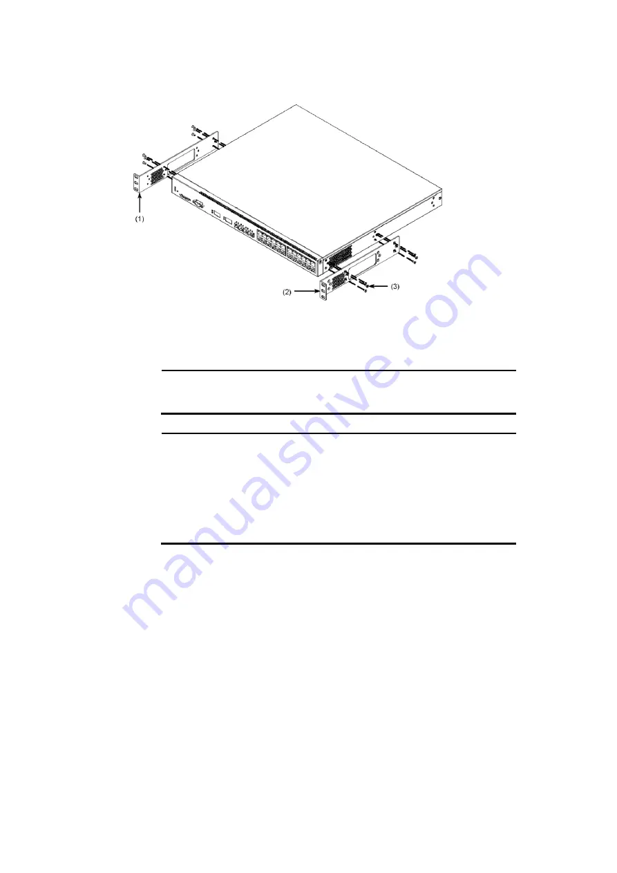
Figure 4-4 

Attaching the rack mounting brackets (50 mm adjustment) (Example for 

AX2400S and AX3600S series switches) 


(1) Rack mounting bracket (L) 

(2) Rack mounting bracket (R) 

(3) M3 x 6 screws (12) 

NOTE


Use the accessory screws to attach the rack mounting brackets to the device. 


NOTE


There are four types of rack mounting brackets: 


For AC and DC models: 12 screw holes 


For AC power (PoE) and redundant power models (AX3630S and AX3640S), 
and EPU: 12 screw holes with label information "24P/EPU" 


For redundant power model (AX3650S): 10 screw holes 


For redundant power model (AX3830S): 20 screw holes 

Confirm that the correct brackets have been selected before attaching the brackets 
to the device. 


[Step 2] 

Mount the EPU into the rack. 

Summary of Contents for AX2400S series

Page 1: ...uction Manual AX36S H001 70X Reading and storing this manual Before you use the equipment carefully read the manual and make sure that you understand all safety precautions After reading the manual store it in a convenient place for easy reference ...

Page 2: ...his Manual Before you use the equipment read the manual carefully and make sure that you understand all safety precautions After reading the manual keep it in a convenient place for easy reference Notes Information in this document is subject to change without notice Radio Interference This switch is a class A information technology device In a domestic environment this product may cause radio int...

Page 3: ...Copyright Copyright C 2005 2011 ALAXALA Networks Corporation All rights reserved ...

Page 4: ......

Page 5: ...cribed Make sure to read them prior to using the Switch Chapter 1 Components Overview An overview of the components of the Switch is provided Chapter 2 Preparation for Installation Environmental conditions and required preparation for installation of the Switch are described Chapter 3 Preparation of Interface Cables and Terminals The interface cables and the terminals used for the Switch are descr...

Page 6: ...Preface II Find description from the AX2400S series manuals ...

Page 7: ...Preface III Find description from the AX3640S and AX3630S series manuals ...

Page 8: ...Preface IV Find description from the AX3800S and AX3650S series manuals How to obtain this manual For the manuals of AX3800S AX3600S and AX2400S series switches see the following ...

Page 9: ...232C SD Secure Digital SFP Small Form factor Pluggable SFP Enhanced Small Form factor Pluggable TCP IP Transmission Control Protocol Internet Protocol T R Transmitter Receiver URL Uniform Resource Locator UTP Unshielded Twisted Pair XFP 10 gigabit small Form factor Pluggable Conventions The terms Switch and switch The term Switch upper case S is an abbreviation for any or all of the following mode...

Page 10: ...Preface VI ...

Page 11: ... 1 14 AX3650S 20S6XW 43 1 1 15 AX3830S 44XW 48 1 1 16 Accessories 52 1 2 Power supply PS 57 1 2 1 PS A01 57 1 2 2 PS D01 58 1 2 3 PS A03 59 1 2 4 Power supply accessories 60 1 3 Fan unit FAN 62 1 3 1 FAN 01 62 1 3 2 FAN 03 63 1 3 3 FAN 04 64 1 3 4 Fan unit accessories 64 1 4 External power unit EPU 66 1 4 1 EPU A 66 1 4 2 EPU B 69 1 4 3 EPU accessories 71 1 5 Power supply module 74 1 5 1 EPU AM 74...

Page 12: ...nting external power units EPUs and power supply modules 140 4 4 1 Table mount 140 4 4 2 Rack mount 141 4 4 3 Inserting and removing power supply modules 143 4 5 Connecting and disconnecting a power cable to and from the main device 146 4 5 1 AC power cable AC power and AC PoE models 146 4 5 2 AC power cable redundant power models AX3630S and AX3640S 148 4 5 3 AC power cable redundant power models...

Page 13: ...193 5 5 Replacement of a fan unit 197 5 5 1 Redundant power model AX3630S AX3640S 197 5 5 2 Redundant power model AX3650S 198 5 5 3 Redundant power model AX3830S 200 5 6 Expansion replacement and removal of external power units EPUs 202 5 7 Expansion replacement and removal of power supply modules 205 Appendixes 207 A Cleaning Optical Connectors 208 A 1 Cleaning optical connectors of transceivers ...

Page 14: ...Contents iv ...

Page 15: ... of this manual Ignoring instructions preceded by this indication and using the Switch incorrectly could result in death or serious injury to yourself and others Ignoring instructions preceded by this indication and using the Switch incorrectly could result in serious injury to yourself and others CAUTION Ignoring instructions preceded by this indication and using the Switch incorrectly could resu...

Page 16: ...rcuit breaker for the electrical power equipment EPU Turn off the EPU and then unplug the power cable Do not allow any foreign objects to get into the Switch Do not insert or drop any foreign objects such as anything metallic or flammable through the Switch s ventilation slots Doing so could result in fire or electric shock When pressing the RESET button do not use anything with a fragile tip or a...

Page 17: ...Safety Information Safety 3 with a liquid such as a vase or a flower pot on the Switch Liquid or metallic objects falling into the Switch could result in a fire or electric shock ...

Page 18: ...dundant power model with DC power supplies use the ground cable for grounding Not connecting the grounded outlet to the switch can cause electric shocks as well as cause failures due to electrical noise A trained engineer or maintenance staff should attach and detach the DC power cable A trained engineer or maintenance staff should connect and disconnect the DC power cable to and from the electric...

Page 19: ...e or electric shock In addition do not use the supplied cable with other devices Doing so could result in a fire or electric shock If the power cable is damaged so that the wires underneath the covering are visible or cut stop using it and ask maintenance personnel to replace it Discontinue using the cable to avoid the risk of fire or electric shock Make sure the power plug is free of dust and ins...

Page 20: ...Safety Information Safety 6 Do not use an air duster near a flame When cleaning the optical connectors do not use an air duster that contains flammable gas near a flame Doing so could result in a fire ...

Page 21: ...ged which might cause a fire Keep more than 50 mm of space from the air vents Do not allow hair or objects near the ventilation slots The Switch has cooling fans Keep any objects away from the air vents Otherwise increasing temperature inside the Switch might cause a failure Do not allow hair or other objects near the ventilation slots They might be sucked into the Switch resulting in injury When ...

Page 22: ... cause the Switch to become deformed or might damage the Switch resulting in fire or electric shock Handle the power cable carefully Do not place the power cable near a heat generating apparatus The heat could melt the cable coating resulting in fire or electric shock When connecting or disconnecting the AC power cable from the outlet always hold the plug not the cable itself Pulling the cable mig...

Page 23: ...l gold and other elements Do not touch the Switch directly if you have an allergic reaction to these metals Doing so might cause eczema or skin irritation Avoid looking directly at laser beams The Switch uses laser beams that are colorless and transparent and invisible to the eye Never look directly into the optical transceiver Do not touch the SFP T and SFP T T during or immediately after operati...

Page 24: ...e and components might cause injury For the redundant power model AX3630S and AX3640S install a fan unit into a slot that does not contain a power supply unit For the redundant power model AX3630S and AX3640S install a fan unit into a slot that does not contain a power supply unit Otherwise the following problems might occur An increase in the temperature inside the switch might cause a failure Th...

Page 25: ...ly module for an EPU is not installed If you use the Switch without attaching the blank panel you might be injured by a moving part In addition if foreign objects fall into the Switch the Switch might no longer work properly Cleaning Remove dust on and around the Switch regularly In addition to possibly causing the Switch to stop accumulated dust might result in fire or electric shock ...

Page 26: ...ir such as the coast An area where corrosive gases are present such as a hot springs area An area where oily smoke is present An area where continuous vibrations are present Ensure that voltage drop does not occur in the power facility due to an inrush current Turning on the Switch causes an inrush current Ensure that voltage drop does not occur in the power facility due to the inrush current Volt...

Page 27: ...re might occur due to increasing temperatures inside the Switch When replacing a fan unit of redundant power models AX3830S Turn off the power before installing or removing a power supply module Before installing or removing a power supply module turn off its power Installing or removing the module with the power supply module turned on causes a Switch failure The following label is attached to th...

Page 28: ...efore removing the card or turning off the power Do not attach any labels to a transceiver or a direct attach cable connector A label attached to the transceiver or direct attach cable connector indicates that the transceiver or direct attach cable connector is a standard product from ALAXALA Networks Corporation or another manufacturer However such labels are attached where they do not interfere ...

Page 29: ... 5 seconds off 0 5 seconds turns to a constant green Otherwise the Switch might break down Updating software When carrying or packing a Switch and an optional module wear a wrist strap to protect against static electricity Be sure to wear an antistatic wrist strap If you handle the Switch without wearing an antistatic wrist strap the Switch might be damaged by static electricity When carrying and ...

Page 30: ...ounterclockwise might damage the ferrule tip Maintenance Clean any dirty areas on the exterior of the switch with a clean dry cloth or a cloth damp with but not soaked with water or a neutral detergent Do not use volatile organic solutions such as benzene or paint thinner chemicals chemically treated cloths or pesticides because these substances might deform discolor or damage the switch If the Sw...

Page 31: ... This chapter provides an overview of the various parts of the Switch 1 1 Main device 1 2 Power supply PS 1 3 Fan unit FAN 1 4 External power unit EPU 1 5 Power supply module 1 6 Memory card 1 7 Transceiver 1 8 Direct attach cable 1 9 Blank panel ...

Page 32: ...rks and server aggregation switches in a server farm The following models belong to the AX3800S AX3600S and AX2400S series Table 1 1 List of AX3800S AX3600S and AX2400S series switches Nu mb er LAN interface Series name Model name 10 100 1 000BAS E T SFP slots SFP slots XFP slots 1 24 ports 4 slots AX2400S AX2430S 24T AC model AX2430S 24TD DC model AX3600S AX3630S 24T AC model AX3630S 24TD DC mode...

Page 33: ...0S 44XW redundant power model 1 1 1 AX2430S 24T AX2430S 24TD AX3630S 24T AX3630S 24TD AX3640S 24T models The AX2430S 24T AX2430S 24TD AX3630S 24T AX3630S 24TD and AX3640S 24T models have the following hardware specifications Ethernet 10 100 1000BASE T ports 24 SFP slots 4 Memory card slot 1 CONSOLE port 1 NOTE Since Switch ports 1 to 4 are shared by the SFP slots and 10 100 1000BASE T the ports ca...

Page 34: ...SE T Ethernet port 5 Security tape NOTE Do not peel away the security tape If you do so will be displayed The device is no longer under warranty if is displayed Figure 1 2 Back view of the AC model 1 Standby power connector with protective cap 2 Cable clamp 3 AC power connector 4 Power switch Figure 1 3 Back view of the DC model ...

Page 35: ...nding by or operating Blinking green Getting ready starting up Blinking red Partial failure with the switch Lit in red Fatal failure in the device operation cannot continue Off Powered off or a failure with a power supply unit 3 ST2 Green LED Not used Off 4 MC Connector Memory card slot Memory card slot 5 ACC Green LED Indicates the memory card status Lit Accessing the memory card Do not remove th...

Page 36: ...in or a paper clip which can be caught or dropped inside the switch and will not be taken out A fire or an electric shock might be caused 1 1 2 AX3640S 24TW The AX3640S 24TW model has the following hardware specifications Ethernet 10 100 1000BASE T ports 24 SFP slots 4 Memory card slot 1 CONSOLE port 1 Power supply unit slots 2 NOTE Since Switch ports 1 to 4 are shared by the SFP slots and 10 100 ...

Page 37: ...minal NOTE To build a redundant power supply system insert power supplies into both power supply unit slots 1 and 2 Otherwise insert a power supply unit into power supply unit slot 1 and a fan unit into power supply unit slot 2 2 Front panel The front panel layout is shown in Figure 1 7 Front panel layout The numbers in the figure correspond to those in Table 1 3 LED indications switches and conne...

Page 38: ...NK Green Orange LED Indicates the operating status of an SFP slot Ethernet port What these LEDs mean depends on the selected LED indication mode from 12 to 15 below For meanings of LED indications see Table 1 4 Operating status in a specific LED indication mode LINK mode to Table 1 6 Operating status in the specific LED indication mode DUPLEX mode 8 T R Green LED 9 1 24 Green Orange LED Indicates ...

Page 39: ...or receiving when the green ST1 LED is lit 9 1 24 Green Orang e LED Indicates the operating status of a 10 100 1000BASE T Ethernet port Lit in green A link is established Blinking green A link is established and frames are being sent or received Lit in orange Detecting line disturbances Off A link failure or block when the green ST1 LED is lit Table 1 5 Operating status in a specific LED indicatio...

Page 40: ...1 3 AX2430S 24T2X AX2430S 24T2XD AX3630S 24T2X AX3630S 24T2XD models The AX2430S 24T2X AX2430S 24T2XD AX3630S 24T2X and AX3630S 24T2XD models have the following hardware specifications Ethernet 10 100 1000BASE T ports 24 SFP slots 4 XFP slots 2 Memory card slot 1 CONSOLE port 1 NOTE Since Switch ports 1 to 4 are shared by the SFP slots and 10 100 1000BASE T the ports cannot be assigned to both SFP...

Page 41: ... under warranty if is displayed Figure 1 9 Back view of the AC model 1 Standby power connector with protective cap 2 Cable clamp 3 AC power connector 4 Power switch Figure 1 10 Back view of the DC model 1 Standby power connector with protective cap 2 DC power connector 2 3 DC power connector 1 4 Power switch 5 Ground terminal 2 Front panel The front panel layout is shown in Figure 1 11 Front panel...

Page 42: ...ff 4 MC Connector Memory card slot Memory card slot 5 ACC Green LED Indicates the memory card status Lit Accessing the memory card Do not remove the memory card Off Memory card is in idle mode The memory card can be removed 6 CONS OLE Connector CONSOLE port RS 232C port to connect a console terminal 7 LINK Green Orang e LED Indicates the operating status of an SFP slot Ethernet port Lit in green A...

Page 43: ...a pin or a paper clip which can be caught or dropped inside the switch and will not be taken out A fire or an electric shock might be caused 1 1 4 AX3640S 24T2XW The AX3640S 24T2XW model has the following hardware specifications Ethernet 10 100 1000BASE T ports 24 SFP slots 4 XFP slots 2 Memory card slot 1 CONSOLE port 1 Power supply unit slots 2 NOTE Since Switch ports 1 to 4 are shared by the SF...

Page 44: ...wer supply unit slot 2 2 Power supply unit slot 1 3 Ground terminal NOTE To build a redundant power supply system insert power supplies into both power supply unit slots 1 and 2 Otherwise insert a power supply unit into power supply unit slot 1 and a fan unit into power supply unit slot 2 2 Front panel The front panel layout is shown in Figure 1 14 Front panel layout The numbers in the figure corr...

Page 45: ...cates the memory card status Lit Accessing the memory card Do not remove the memory card Off Memory card is in idle mode The memory card can be removed 6 CONS OLE Connector CONSOLE port RS 232C port to connect a console terminal 7 LINK Green Orang e LED Indicates the operating status of an SFP slot Ethernet port What these LEDs mean depends on the selected LED indication mode from 14 to 17 below F...

Page 46: ...en out A fire or an electric shock might be caused Table 1 9 Operating status in a specific LED indication mode LINK mode Num ber Name Type Description Details 7 LINK Green Orang e LED Indicates the operating status of an SFP slot Ethernet port Lit in green A link is established Lit in orange Detecting line disturbances Off A link failure or block when the green ST1 LED is lit 8 T R Green LED Blin...

Page 47: ...isturbances 10 T R Green LED Not used Off 11 1 24 Green Orange LED Indicates the operating status of a 10 100 1000BASE T Ethernet port Lit in green 100 Mbps 1 Blinking green 1000 Mbps 1 Lit in orange Detecting line disturbances Off 10 Mbps 1 1 These indications are valid after a link is established Table 1 11 Operating status in the specific LED indication mode DUPLEX mode Num ber Name Type Descri...

Page 48: ...igned to an SFP slot or as a 10 100 1000BASE T port By default ports 1 to 4 are SFP slots For details about editing the configuration see the Software Manual NOTE The Type A PoE system Alternative A is used for the Switch For details see 3 2 1 Ethernet 10 100 1000BASE T NOTE For information about the SFPs supported by the Switch see 1 7 1 SFP 1 External appearance Figure 1 15 Front view 1 Memory c...

Page 49: ...indications switches and connectors Num ber Name Type Description Details 1 PWR Green LED Indicates the power supply status Lit in green Powered on Off Powered off or a failure with a power supply unit 2 ST1 Green Red LED Indicates the device status Lit in green Standing by or operating Blinking green Getting ready starting up Blinking red Partial failure with the switch Lit in red Fatal failure i...

Page 50: ... or block when the green ST1 LED is lit 10 RESET Button momentary Manual RESET button of the device 1 Restarts the device 1 The switch is behind the front panel Use a small head screwdriver to press it When attempting to push the RESET button do not use a tool with a fragile tip a pin or a paper clip which can be caught or dropped inside the switch and will not be taken out A fire or an electric s...

Page 51: ...SE T Ethernet port 5 Security tape NOTE Do not peel away the security tape If you do so will be displayed The device is no longer under warranty if is displayed Figure 1 19 Back view of the AC model 1 Standby power connector with protective cap 2 Cable clamp 3 AC power connector 4 Power switch Figure 1 20 Back view of the DC model ...

Page 52: ...Standing by or operating Blinking green Getting ready starting up Blinking red Partial failure with the switch Lit in red Fatal failure in the device operation cannot continue Off Powered off or a failure with a power supply unit 3 ST2 Green LED Not used Off 4 MC Connector Memory card slot Memory card slot 5 ACC Green LED Indicates the memory card status Lit Accessing the memory card Do not remove...

Page 53: ...hich can be caught or dropped inside the switch and will not be taken out A fire or an electric shock might be caused 1 1 7 AX3630S 48TW AX3640S 48TW models The AX3630S 48TW and AX3640S 48TW models have the following hardware specifications Ethernet 10 100 1000BASE T ports 48 SFP slots 4 Memory card slot 1 CONSOLE port 1 Power supply unit slots 2 NOTE Since Switch ports 1 to 4 are shared by the SF...

Page 54: ...ower supplies into both power supply unit slots 1 and 2 Otherwise insert a power supply unit into power supply unit slot 1 and a fan unit into power supply unit slot 2 2 Front panel The front panel layout is shown in Figure 1 24 Front panel layout The numbers in the figure correspond to those in Table 1 14 LED indications switches and connectors Figure 1 24 Front panel layout Table 1 14 LED indica...

Page 55: ...orange Detecting line disturbances Off A link failure or block when the green ST1 LED is lit 8 T R Green LED Blinking green Frames are being sent or received 9 1 48 Green Orang e LED Indicates the operating status of a 10 100 1000BASE T Ethernet port Lit in green A link is established Blinking green A link is established and frames are being sent or received Lit in orange Detecting line disturbanc...

Page 56: ... NOTE Do not peel away the security tape If you do so will be displayed The device is no longer under warranty if is displayed Figure 1 26 Back view of the AC model 1 Standby power connector with protective cap 2 Cable clamp 3 AC power connector 4 Power switch 2 Front panel The front panel layout is shown in Figure 1 27 Front panel layout The numbers in the figure correspond to those in Table 1 15...

Page 57: ...d Do not remove the memory card Off Memory card is in idle mode The memory card can be removed 6 CONS OLE Connector CONSOLE port RS 232C port to connect a console terminal 7 LINK Green Orang e LED Indicates the operating status of an XFP slot Ethernet port Lit in green A link is established Lit in orange Detecting line disturbances Off A link failure or block when the green ST1 LED is lit 8 T R Gr...

Page 58: ...AX3640S 48T2XW models have the following hardware specifications Ethernet 10 100 1000BASE T ports 48 XFP slots 2 Memory card slot 1 CONSOLE port 1 Power supply unit slots 2 NOTE For information about the XFPs supported by the Switch see 1 7 3 XFP 1 External appearance Figure 1 28 Front view 1 Memory card slot 2 CONSOLE port 3 XFP slot 4 10 100 1000BASE T Ethernet port 5 Security tape NOTE Do not p...

Page 59: ...ure correspond to those in Table 1 16 LED indications switches and connectors Figure 1 30 Front panel layout Table 1 16 LED indications switches and connectors Num ber Name Type Description Details 1 PWR Green LED Indicates the power supply status Lit in green Powered on Off Powered off or a failure with a power supply unit 2 ST1 Green Red LED Indicates the device status Lit in green Standing by o...

Page 60: ...sturbances Off A link failure or block when the green ST1 LED is lit 10 RESET Button momentary Manual RESET button of the device 1 Restarts the device 1 The switch is behind the front panel Use a small head screwdriver to press it When attempting to push the RESET button do not use a tool with a fragile tip a pin or a paper clip which can be caught or dropped inside the switch and will not be take...

Page 61: ...igure 1 32 Back view 1 Power supply unit slot 2 2 Power supply unit slot 1 3 Ground terminal NOTE To build a redundant power supply system insert power supplies into both power supply unit slots 1 and 2 Otherwise insert a power supply unit into power supply unit slot 1 and a fan unit into power supply unit slot 2 2 Front panel The front panel layout is shown in Figure 1 33 Front panel layout The n...

Page 62: ...y card Do not remove the memory card Off Memory card is in idle mode The memory card can be removed 6 CONS OLE Connector CONSOLE port RS 232C port to connect a console terminal 7 LINK Green Orange LED Indicates the operating status of a 10 100 1000BASE T Ethernet port Lit in green A link is established Lit in orange Detecting line disturbances Off A link failure or block when the green ST1 LED is ...

Page 63: ... 1 CONSOLE port 1 Power supply unit slots 2 NOTE Since Switch ports 1 to 4 are shared by the SFP slots and 10 100 1000BASE T the ports cannot be assigned to both SFP and 10 100 1000BASE T at the same time Configure each port so that it is either assigned to an SFP slot or as a 10 100 1000BASE T port By default ports 1 to 4 are SFP slots For details about editing the configuration see the Software ...

Page 64: ... 1 and 2 Otherwise insert a power supply unit into power supply unit slot 1 and a fan unit into power supply unit slot 2 2 Front panel The front panel layout is shown in Figure 1 36 Front panel layout The numbers in the figure correspond to those in Table 1 18 LED indications switches and connectors Figure 1 36 Front panel layout Table 1 18 LED indications switches and connectors Num ber Name Type...

Page 65: ...failure or block when the green ST1 LED is lit 8 T R Green LED Blinking green Frames are being sent or received 9 LINK Green Orange LED Indicates the operating status of an SFP slot Ethernet port Lit in green A link is established Lit in orange Detecting line disturbances Off A link failure or block when the green ST1 LED is lit 10 T R Green LED Blinking green Frames are being sent or received 11 ...

Page 66: ...t slots 2 Fan unit slot 1 NOTE For information about the SFPs and SFP s supported by the Switch see 1 7 1 SFP and 1 7 2 SFP 1 External appearance Figure 1 37 Front view 1 10 100 1000BASE T Ethernet port 2 Memory card slot 3 SFP slot 4 CONSOLE port 5 System operation panel 6 Security tape NOTE Do not peel away the security tape If you do so will be displayed The device is no longer under warranty i...

Page 67: ...e front panel layout is shown in Figure 1 39 Front panel layout The numbers in the figure correspond to those in Table 1 19 LED indications switches and connectors AX3650 24T6XW switches support the device sleep function and LED brightness control function power control brightness mode and off mode in order to save power Figure 1 39 Front panel layout ...

Page 68: ...ith the switch Low 2 Lit in red Normal Fatal failure in the device operation cannot continue Low 2 Off Powered off or a failure with a power supply unit 3 MC Conne ctor Memory card slot Memory card slot 4 ACC Green LED Indicates the memory card status Lit Normal Accessing the memory card Do not remove the memory card Low 2 Off Memory card is in idle mode The memory card can be inserted or removed ...

Page 69: ...Button Not supported 12 ENTR Button 13 FWRD Button 1 Blinking green over a long period of time on 0 5 seconds off 5 seconds 2 Operating in power control brightness mode or off mode 3 Operating in power control brightness mode 4 In off mode a link might be established frames might be sent or received or line disturbances might be detected 5 The switch is behind the front panel Use a small head scre...

Page 70: ...1 7 2 SFP 1 External appearance Figure 1 40 Front view 1 Memory card slot 2 10 100 1000BASE T Ethernet port 3 SFP slot 4 CONSOLE port 5 System operation panel 6 Security tape NOTE Do not peel away the security tape If you do so will be displayed The device is no longer under warranty if is displayed Figure 1 41 Back view 1 Fan unit slot 2 Ground terminal ...

Page 71: ... in Figure 1 42 Front panel layout The numbers in the figure correspond to those in Table 1 20 LED indications switches and connectors AX3650S 48T4XW switches support the device sleep function and LED brightness control function power control brightness mode and off mode in order to save power Figure 1 42 Front panel layout ...

Page 72: ...with the switch Low 2 Lit in red Normal Fatal failure in the device operation cannot continue Low 2 Off Powered off or a failure with a power supply unit 3 MC Connector Memory card slot Memory card slot 4 ACC Green LED Indicates the memory card status Lit Normal Accessing the memory card Do not remove the memory card Low 2 Off Memory card is in idle mode The memory card can be inserted or removed ...

Page 73: ...rted 11 BACK Button Not supported 12 ENTR Button 13 FWRD Button 1 Blinking green over a long period of time on 0 5 seconds off 5 seconds 2 Operating in power control brightness mode or off mode 3 Operating in power control brightness mode 4 In off mode a link might be established frames might be sent or received or line disturbances might be detected 5 The switch is behind the front panel Use a sm...

Page 74: ...pported by the Switch see 1 7 1 SFP and 1 7 2 SFP 1 External appearance Figure 1 43 Front view 1 SFP slot 2 Memory card slot 3 10 100 1000BASE T Ethernet port 4 SFP slot 5 CONSOLE port 6 System operation panel 7 Security tape NOTE Do not peel away the security tape If you do so will be displayed The device is no longer under warranty if is displayed ...

Page 75: ...e front panel layout is shown in Figure 1 45 Front panel layout The numbers in the figure correspond to those in Table 1 21 LED indications switches and connectors AX3650 20S6XW switches support the device sleep function and LED brightness control function power control brightness mode and off mode in order to save power Figure 1 45 Front panel layout ...

Page 76: ...ng red Normal Partial failure with the switch Low 2 Lit in red Normal Fatal failure in the device operation cannot continue Low 2 Off Powered off or a failure with a power supply unit 3 MC Connector Memory card slot Memory card slot 4 ACC Green LED Indicates the memory card status Lit Normal Accessing the memory card Do not remove the memory card Low 2 Off Memory card is in idle mode The memory ca...

Page 77: ... is lit 4 9 T R Green LED Blinking green Normal Sending or receiving frames Low 3 10 LINK Green Ora nge LED Indicates the operating status of a 10 100 1000BASE T Ethernet port Lit in green Normal A link is established Low 3 Lit in orange Normal Detecting line disturbances Low 3 Off A link failure or block when the green ST1 LED is lit 4 11 T R Green LED Blinking green Normal Sending or receiving f...

Page 78: ...le tip a pin or a paper clip which can be caught or dropped inside the switch and will not be taken out A fire or an electric shock might be caused 1 1 15 AX3830S 44XW The AX3830S 44XW model has the following hardware specifications Ethernet 10 100 1000BASE T ports 4 SFP slots 44 Memory card slot 1 CONSOLE port 1 Power supply unit slots 2 Fan unit slot 1 NOTE For information about the SFPs and SFP...

Page 79: ...2 2 Fan unit slot 3 Ground terminal 4 Power supply unit slot 1 2 Front panel The front panel layout is shown in Figure 1 48 Front panel layout The numbers in the figure correspond to those in Table 1 22 LED indications switches and connectors AX3830S 44XW supports the device sleep function and LED brightness control function power control brightness mode and off mode Figure 1 48 Front panel layout...

Page 80: ...ng red Normal Partial failure with the switch Low 2 Lit in red Normal Fatal failure in the device operation cannot continue Low 2 Off Powered off or a failure with a power supply unit 3 MC Connector Memory card slot Memory card slot 4 ACC Green LED Indicates the memory card status Lit Normal Accessing the memory card Do not remove the memory card Low 2 Off Memory card is in idle mode The memory ca...

Page 81: ...D Not used Off 11 ID1 to ID4 Green LED Not used Off 12 RESET Button momentary Manual RESET button of the device 5 Restarts the device 13 MODE Button momentary Not used 1 Blinking green over a long period of time on 0 5 seconds off 5 seconds 2 Operating in power control brightness mode or off mode 3 Operating in power control brightness mode 4 In off mode a link might be established frames might be...

Page 82: ... to using a switch Yes Yes Yes Yes 1 switch is replaced with the series name 2 For Safe Operation Yes Yes Yes Yes 1 3 Software License Agreement Yes Yes Yes Yes 1 4 AC power cable Yes 1 3m 5 DC power cable Yes 1 3m 6 Ground cable Yes 1 3m 7 Rubber pad Yes Yes Yes Yes 4 8 Rack mounting bracket Yes Yes Yes 2 1 each for left and right Yes 6 One left bracket and one right bracket for the front surface...

Page 83: ...n the Switch Be sure to read through this document before using the switch 4 AC power cable The cable 3 m long is for a 100 V AC power supply unit This item is bundled with AC power and AC PoE models Figure 1 49 AC power cable Make sure to use the accessory power cable when any AC power or AC PoE model is connected to 100 V AC Other cable except the bundled one may cause a fire and or an electric ...

Page 84: ... accessory cable only for the Switch Otherwise a fire and or an electric shock may be the result NOTE Optional DC power cables are available Use an optional one when a DC model is connected to two power supply systems 6 Ground cable Three meter ground cable shown in Figure 1 51 Ground cable is bundled with DC models Figure 1 51 Ground cable 7 Rubber pad Use these pads to install the product on a t...

Page 85: ...racket L 2 Rack mounting bracket R Figure 1 54 Rack mounting brackets for AC PoE and redundant power models AX3630S and AX3640S 1 Rack mounting bracket L 2 Rack mounting bracket R Figure 1 55 Rack mounting brackets for redundant power model AX3650S 1 Rack mounting bracket L 2 Rack mounting bracket R ...

Page 86: ...t power model AX3830S 20 screw holes Confirm that the correct brackets have been selected before attaching the brackets to the device 9 Screws Use the screws to attach the rack mounting brackets to the device Figure 1 57 Screws AX2400S and AX3600S Figure 1 58 Screws AX3830S 10 Dummy memory card When no memory card is used insert this item to the memory card slot of the device as a substitute Keep ...

Page 87: ...power supplies Table 1 24 Available combinations of switches and power supplies Series Model name Compatible power supply 100 V AC and 200 V AC 48 V DC AX3630S AX3630S 48TW AX3630S 48T2XW AX3630S 24S2XW PS A01 PS D01 AX3640S AX3640S 24TW AX3640S 24T2XW AX3640S 48TW AX3640S 48T2XW AX3640S 24SW AX3640S 24S2XW AX3650S AX3650S 24T6XW AX3650S 48T4XW AX3650S 20S6XW PS A03 AX3830S AX3830S 44XW 1 2 1 PS A...

Page 88: ...tection 1 Off Normal 3 ALM2 Red LED Indicates a failure with the integrated fan Lit in red Fault detection 1 Off Normal 1 In some cases of a failure none of the POWER ALM1 and ALM2 LEDs are turned on or only the ALM2 LED is lit 1 2 2 PS D01 PS D01 is a power supply unit for the redundant power models in the AX3630S and AX3640S series This power supply unit supports 48 V DC Figure 1 61 External app...

Page 89: ... the integrated fan Lit in red Fault detection 1 Off Normal 1 In some cases of a failure none of the POWER ALM1 and ALM2 LEDs are turned on or only the ALM2 LED is lit 1 2 3 PS A03 PS A03 is a power supply unit for the redundant power models in the AX3830S and AX3650S series This power supply unit supports 100 V AC and 200 V AC Figure 1 62 External appearance shows its appearance For the LEDs in t...

Page 90: ... supply accessories The items listed in Table 1 28 Power supply accessories are included as accessories with shipment of the power supply unit Table 1 28 Power supply accessories Numb er Item Quantity Notes 1 Check list for bundled items 1 2 For Safe Operation 1 3 AC power cable 1 3 m for PS A01 and PS A03 4 Ground cable 1 3 m PS D01 only 1 Check list for bundled items List of the bundled items wi...

Page 91: ...rwise a fire or an electric shock might result NOTE For required specifications of power cables see 2 3 2 Electrical power equipment for 200 V AC 4 Ground cable The cable 3 m long is for grounding Use it when a PS D01 is inserted into any redundant power model AX3630S or AX3640S This item is bundled with a PS D01 Figure 1 64 Ground cable A PS D01 does not have an accessory power cable Make sure to...

Page 92: ...s Model name Compatible fan unit AX3630S AX3630S 48TW AX3630S 48T2XW AX3630S 24S2XW FAN 01 AX3640S AX3640S 24TW AX3640S 24T2XW AX3640S 48TW AX3640S 48T2XW AX3640S 24SW AX3640S 24S2XW AX3650S AX3650S 24T6XW AX3650S 48T4XW AX3650S 20S6XW FAN 03 AX3830S AX3830S 44XW FAN 04 1 3 1 FAN 01 FAN 01 is a fan unit for the redundant power models in the AX3630S and AX3640S series When only one power supply uni...

Page 93: ... power models in the AX3650S series It is inserted into the fan unit slot on the chassis regardless of the number of power supply units Figure 1 66 External appearance shows its appearance For the LEDs in the figure see Table 1 31 LED indication Figure 1 66 External appearance 1 ALM LED 2 Latch 3 Handle Table 1 31 LED indication Nu mb er Name Type Description Details 1 ALM Red LED Indicates fan fa...

Page 94: ...Details 1 ALM Red LED Indicates fan failure Lit in red Fault detection 1 Off Normal 1 LED is turned off in the sleep mode NOTE Four fan components are installed in the fan unit This enables uninterrupted operation and cooling performance even if one of the four fan components fails However if the fan unit has failed replace it To replace the fan unit see 5 5 Replacement of a fan unit 1 3 4 Fan uni...

Page 95: ...1 Check list for bundled items List of the bundled items with shipment of the fan unit 2 For Safe Operation Cautionary notes for safe use of the Switch are described Be sure to read through this document before using the switch ...

Page 96: ...n power supply modules One power supply module can serve as the stand by power supply unit for one switch By adding power supply modules to an EPU standby power can be supplied to up to four switches EPU A or two switches EPU B Table 1 34 Compatibility of main devices with external power units EPUs and power supply modules Main Device Compatible EPU Compatible power supply module Power supply type...

Page 97: ...y tape If you do so will be displayed The device is no longer under warranty if is displayed Figure 1 69 Back view 1 Standby power connectors 4 2 Cable clamp 3 AC power connector 4 Main power switch 2 Panel layout The front layout and back layout are shown in Figure 1 70 Front layout and Figure 1 71 Back layout respectively The numbers in the figure correspond to those in Table 1 35 LED indication...

Page 98: ...Red LED Indicates the power output status from the power supply modules Lit in red Output power failure from the power supply modules Off Normal output from the power supply modules or powered off 4 EPU 1 Connector Standby power connector 1 To output electrical power from the power supply module mounted in slot 1 Connect the standby power cable bundled with the EPU to the standby power connector o...

Page 99: ...anels over the other slots when shipped 1 External appearance Figure 1 72 Front view 1 Power switches for the power supply modules 2 2 Power supply module EPU BM mounted in slot 1 when shipped 3 Blank panel 4 Power supply module slots 2 5 Security tape NOTE Do not peel away the security tape If you do so will be displayed The device is no longer under warranty if is displayed Figure 1 73 Back view...

Page 100: ... LED Indicates the power output status from the power supply modules Lit in green Normal output from the power supply modules Off Output power failure from the power supply modules or powered off 3 DC FAIL Red LED Indicates the power output status from the power supply modules Lit in red Output power failure from the power supply modules Off Normal output from the power supply modules or powered o...

Page 101: ...pment of an EPU Table 1 37 EPU accessories Nu mb er Item Quantit y Notes 1 Check list for bundled items 1 2 For Safe Operation 1 3 AC power cable 1 3m 4 Standby power cable 1 1 5m 5 Rubber pad 4 6 Rack mounting bracket 2 1 each for left and right 7 Screws 12 M3 x 6 1 Check list for bundled items List of the bundled items with shipment of the EPU 2 For Safe Operation Cautionary notes for safe use o...

Page 102: ... Standby power cable Make sure to use the accessory power cable Other cable except the bundled one may cause a fire and or an electric shock In addition use the accessory cable only for the Switch Otherwise a fire and or an electric shock may be the result NOTE There are two types of standby power cables for EPU A and EPU B The cable for EPU A has a tag labeled EPU A C CABLE and the cable for EPU ...

Page 103: ...or AC power PoE and redundant power models AX3630S and AX3640S and EPU 12 screw holes with label information 24P EPU For redundant power model AX3650S 10 screw holes For redundant power model AX3830S 20 screw holes Confirm that the correct brackets have been selected before attaching the brackets to the device 7 Screws Use the screws to attach the rack mounting brackets to the EPU Figure 1 80 Scre...

Page 104: ...ows its appearance For descriptions about 1 and 2 in the figure see Table 1 38 LED indication Figure 1 81 External appearance 1 DC OK LED 2 DC ALM LED 3 Handle 4 Latch 5 Power switch Table 1 38 LED indications Nu mb er Name Type Description Details 1 DC OK Green LED Indicates the power output status from the power supply modules Lit in green Normal output from the power supply modules Off Output p...

Page 105: ...d off 2 DC FAIL Red LED Indicates the power output status from the power supply modules Lit in red Output power failure from the power supply modules Off Normal output from the power supply modules or powered off 3 AC OK Green LED Indicates the power input status to the power supply modules Lit in green Normal input to the power supply modules Off Input power failure to the power supply modules or...

Page 106: ...power cable Standby power cable 1 5 meter long Use it to connect the EPU to the main device Figure 1 83 Standby power cable Make sure to use the accessory power cable Other cable except the bundled one may cause a fire and or an electric shock In addition use the accessory cable only for the Switch Otherwise a fire and or an electric shock may be the result NOTE There are two types of standby powe...

Page 107: ...ware 1 SD128 and SD128 T Below is an SD memory card with a 128 MB capacity Figure 1 84 External appearance Label information AlaxalA SD128 or AlaxalA SD128 T 2 SD1G Below is an SD memory card with a 1 GB capacity Figure 1 85 External appearance Label information AlaxalA SD1G NOTE Make sure to use our standard products with the label shown in the figure Otherwise correct operation is not guaranteed...

Page 108: ...mand For details about the show port command see 14 Ethernet in the Software Manual Configuration Guide Vol 1 Table 1 41 SFP list Num ber Module name Interface Supported models 1 SFP T SFP T T Ethernet 10 100 1000BASE T PoE not supported AX3630S 24S2XW 1 AX3640S 24SW 1 AX3640S 24S2XW 1 AX3650S 20S6XW 2 AX3830S series 5 2 SFP FX SFP FX T Ethernet 100BASE FX AX3640S 24SW 1 AX3640S 24S2XW 1 AX3650S 2...

Page 109: ...SFP T T transceivers use laser beams that are colorless and invisible Do not directly look into the optical transmitter receiver part CAUTION Do not attach other labels to the transceiver The transceivers have labels to certify that they are standard products of the manufacturer or ALAXALA Networks Corporation These labels are attached so as not to disturb heat radiation from the transceiver or th...

Page 110: ...PoE is not supported 2 SFP FX and SFP FX T Figure 1 87 External appearance 1 Label information AlaxalA SFP FX or AlaxalA SFP FX T Label color White 2 Handle color Black CAUTION SFP FX and SFP FX T are supported by the switches below Use them only with the indicated switches Otherwise the switch might fail AX3640S 24SW target ports 5 to 24 AX3640S 24S2XW target ports 5 to 24 AX3650S 20S6XW target p...

Page 111: ...se them only with the indicated switches Otherwise the switch might fail AX2430S series AX3630S series AX3640S series AX3650S 20S6XW target ports 1 to 20 5 SFP LX and SFP LX T Figure 1 90 External appearance 1 Label information AlaxalA SFP LX or AlaxalA SFP LX T Label color Blue 2 Handle color Blue 6 SFP LH and SFP LH T Figure 1 91 External appearance 1 Label information AlaxalA SFP LH or AlaxalA ...

Page 112: ...2 Handle color Yellow green 8 SFP BX1U and SFP BX1U T Figure 1 93 External appearance 1 SFP back label information AlaxalA SFP BX1U or AlaxalA SFP BX1U T Label color White 2 Handle color Blue 9 SFP BX1D and SFP BX1D T Figure 1 94 External appearance 1 SFP back label information AlaxalA SFP BX1D or AlaxalA SFP BX1D T Label color White 2 Handle color Magenta ...

Page 113: ...4D or AlaxalA SFP BX4D T Label color White 2 Handle color Green 1 7 2 SFP To use an SFP insert it into a switch SFP slot The SFP type can be identified by the label information or the handle color The SFP transceivers supported by the Switch are listed in Table 1 42 SFP list Table 1 42 SFP list Nu mbe r Module name Interface Supported models 1 SFPP SR 10 gigabit Ethernet 10GBASE SR AX3650S series ...

Page 114: ...radiation from the transceiver or the mechanism to avoid dropping from the cage Attaching a label on an interfering part with heat radiation or the mechanism to avoid dropping from the cage might cause a failure in the transceiver or damage to the device NOTE Make sure to use our standard products with the label shown in the figure Otherwise correct operation is not guaranteed 1 SFPP SR Figure 1 9...

Page 115: ... 3 XFP ER XFP ER T 10 Gigabit Ethernet 10GBASE ER 4 XFP ZR XFP ZR T 10 Gigabit Ethernet 10GBASE ZR Laser beam which is colorless and invisible is used Do not directly look into the optical transmitter receiver part CAUTION Do not attach other labels to the transceiver The transceivers have labels to certify that they are standard products of the manufacturer or ALAXALA Networks Corporation These l...

Page 116: ...rance 1 Label information AlaxalA XFP SR or AlaxalA XFP SR T 2 Handle color Ivory 2 XFP LR and XFP LR T Figure 1 101 External appearance 1 Label information AlaxalA XFP LR or AlaxalA XFP LR T 2 Handle color Blue NOTE XFP LR and XFP LR T transceivers have two types the module A type and the module B type There is no difference between the types 3 XFP ER and XFP ER T Figure 1 102 External appearance...

Page 117: ... items listed in Table 1 44 Transceiver accessories are included as accessories with shipment of the transceiver Table 1 44 Transceiver accessories Nu mb er Item Quantit y Notes 1 Check list for bundled items 1 2 For Safe Operation 1 1 Check list for bundled items List of the bundled items with shipment of the transceiver 2 For Safe Operation Cautionary notes for safe use of the Switch are describ...

Page 118: ...axalA SFPP CU5M 1 SFPP CU1M SFPP CU3M and SFPP CU5M Figure 1 104 1 Connector CAUTION Do not attach other labels to the connector The connectors have labels to certify that they are standard products of the manufacturer or ALAXALA Networks Corporation These labels are attached so as not to disturb heat radiation from the connector or the mechanism to avoid dropping from the cage Attaching a label o...

Page 119: ...1 Components Overview 89 NOTE Make sure to use our standard products with the label shown in the table Otherwise correct operation is not guaranteed ...

Page 120: ...nents Overview 90 1 9 Blank panel Blank panels are attached instead of power supplies when only one power supply unit is installed in AX3830S or AX3650S series switches 1 BPNL 01 Figure 1 105 1 Handle 2 Screws ...

Page 121: ...ation read this chapter carefully and make sure that you understand all instructions and cautionary notes in this chapter 2 1 Preparation workflow 2 2 Installation conditions 2 3 Electrical power equipment 2 4 Notes on electrical noise 2 5 Leakage current 2 6 Environmental conditions 2 7 Where to install 2 8 Maintenance area 2 9 Cooling conditions 2 10 Noise of the Switch ...

Page 122: ...n is shown in Figure 2 1 Flowchart of the installation preparation The workflow for supplying power communication functions and LAN cable installation should be completed prior to carrying in the components Make sure to schedule them in good time Figure 2 1 Flowchart of the installation preparation ...

Page 123: ...5 kg or less 5 5 kg or less 5 kg or less 5 5 kg or less Input voltage Rating Single phase AC 100 to 120 V 200 to 240 V 3 48 V DC Variation range 90 to 127 2 V AC 180 to 254 4 V AC 40 to 57 V DC Frequency 50 60 3Hz Maximum input current 0 8A 100 V AC 0 9A 100 V AC 1 2A 100 V AC 1 3A 100 V AC 1 5A 48 V DC 1 7A 48 V DC 2 5A 48 V DC 0 4A 200 V AC 0 5A 200 V AC 0 6A 200 V AC 0 7A 200 V AC Maximum power...

Page 124: ...9 A 100 V AC 5 8 A 100 V AC 1 5 A 48 V DC 1 8 A 48 V DC 0 4 A 200 V AC 0 5 A 200 V AC Maximum power consumption 75 W 89 W 580 W 70 W 82 W Maximum heat emission 270kJ h 321 kJ h 757 kJ h 4 252 kJ h 296 kJ h 1 Excluding the dimensions of connectors 2 Weight of the main device only The weight of cables rack mounting brackets memory cards and transceivers are excluded 3 The power cable bundled with th...

Page 125: ...00 V AC 2 6A 48 V DC 1 5A 100 V AC 2 8A 48 V DC 0 5A 200 V AC 0 7A 200 V AC 0 8A 200 V AC Maximum power consumption 92 W 85 W 134 W 124 W 143 W 133 W Maximum heat emission 332 kJ h 306 kJ h 483 kJ h 447 kJ h 515 kJ h 479 kJ h 1 Excluding the dimensions of connectors and handles 2 Weight of the main device with two power supplies However the weight of cables rack mounting brackets memory cards and ...

Page 126: ...1 2 Item Model name AX3640S 24TW AX3640S 24T2XW AX3640S 48TW PS A01 mounted PS D01 mounted PS A01 mounted PS D01 mounted PS A01 mounted PS D01 mounted Dimensions W x D x H 1 445 x 440 x 43 mm Weight 2 9 kg or less Input voltage Rating Single phase 100 to 120 V AC 200 to 240 V AC 3 48 V DC Single phase 100 to 120 V AC 200 to 240 V AC 3 48 V DC Single phase 100 to 120 V AC 200 to 240 V AC 3 48 V DC ...

Page 127: ... to 100 V AC Table 2 6 General installation conditions for AX3640S series switches redundant power models 2 2 Item Model name AX3640S 48T2XW AX3640S 24SW AX3640S 24S2XW PS A01 mounted PS D01 mounted PS A01 mounted PS D01 mounted PS A01 mounted PS D01 mounted Dimensions W x D x H 1 445 x 440 x 43 mm Weight 2 9 kg or less Input voltage Rating Single phase 100 to 120 V AC 200 to 240 V AC 3 48 V DC Si...

Page 128: ...al installation conditions for AX3650S series switches Item Model name AX3650S 24T6XW AX3650S 48T4XW AX3650S 20S6XW PS A03 mounted PS A03 mounted PS A03 mounted Dimensions W x D x H 1 445 x 500 x 43 mm Weight 2 9 kg or less Input voltage Rating Single phase 100 to 120 V AC 200 to 240 V AC 3 Variation range 90 to 127 2 V AC 180 to 254 4 V AC Frequency 50 60 3Hz Maximum input current 1 1A 100 V AC 1...

Page 129: ...0kJ h 1 Excluding the dimensions of connectors 2 Weight of the main device with two power supplies and one fan unit However the weight of cables rack mounting brackets memory cards and transceivers are excluded 3 The power cable bundled with the Switch is only applicable to 100 V AC Table 2 9 General installation conditions for external power units EPUs Item Model name EPU A EPU B Dimensions W x D...

Page 130: ...Environmental conditions AC models DC models AC PoE models and EPU models Item Requirement Device EPU AC model DC model AC PoE model EPU A EPU B Noise 1 45 dB or less 50 dB or less 2 45 dB or less 50 dB or less 2 Vibration 2 45 m s 2 or less Dust 0 15 mg m3 or less 3 Temperatu re Operating 0 to 40 deg C 23 to 28 deg C recommended 4 0 to 40 deg C 23 to 28 deg C recommended Not operating 10 to 43 de...

Page 131: ...1 Noise 2 3 25 deg C 35 dB or less 45 dB or less 37 dB or less 45 dB or less 65 dB or less 69 dB or less 30 deg C 35 deg C 40 deg C 45 dB or less 45 dB or less 69 dB or less 50 deg C 52 dB or less 52 dB or less 73 dB or less 73 dB or less Vibration 2 45 m s 2 or less Dust 0 15 mg m3 or less 4 Temperatu re Operating 0 to 40 deg C 23 to 28 deg C recommended 5 10 to 50 deg C 23 to 28 deg C recommende...

Page 132: ...e exceeds 50 deg C the Switch stops 6 If the temperature sensor for the intake air temperature exceeds 60 deg C the Switch stops 7 When starting the switch make sure that the temperature is in the range from 0 to 50 deg C 8 No condensation NOTE For details about the operating mode of a switch s fan see the manual Operation Command Reference NOTE The intake air temperature can be checked by using t...

Page 133: ... to the switch can cause electric shocks as well as cause failures due to electrical noise 2 Distribution board The branch circuit to supply power to the Switch requires circuit breakers or other devices When selecting circuit breakers make sure that they meet the following rating considering the input current and inrush current time Breaker rating 15 AT single phase 100 V AC for a 15 A circuit or...

Page 134: ... incoming current to the distribution board should be larger than the breaker operating current capacity Otherwise the breakers cannot operate properly in case of trouble which might cause a fire NOTE Generally the breaker operating current is larger than the rated current Check the specifications of the circuit breaker In addition if you power on the Switch it has inrush current listed in Table 2...

Page 135: ...d outlet to the switch can cause electric shocks as well as cause failures due to electrical noise 3 Distribution board The branch circuit to supply power to the Switch requires circuit breakers or other devices When selecting circuit breakers make sure that they meet the following rating considering the input current and inrush current time Breaker rating 10 AT single phase 200 V AC for a 10 A ci...

Page 136: ...n addition if you power on the Switch it has inrush current listed in Table 2 15 Inrush current Consider measures to prevent voltage reduction of the power supply due to inrush current CAUTION If you power on the Switch it has inrush current Consider measures to prevent voltage reduction of the power supply due to inrush current If voltage reduction occurs not only the Switch but also other device...

Page 137: ...l power equipment Wrong handling of the DC power cable can cause a fire or an electric shock Prior to connecting or disconnecting the DC power cable turn off the circuit breaker of the electrical power equipment Otherwise an electric shock might result Cover the G and 48 V terminals of the DC power cable on the electrical power equipment side with an insulation jacket Otherwise an electric shock m...

Page 138: ...be larger than that of the breaker operating current Ensure that the capacity of incoming current to the distribution board should be larger than the breaker operating current capacity Otherwise the breakers cannot operate properly in case of trouble which might cause a fire NOTE Generally the breaker operating current is larger than the rated current Check the specifications of the circuit breake...

Page 139: ... or disconnecting the DC power cable turn off the circuit breaker of the electrical power equipment Otherwise an electric shock might result Peel the DC power cable jackets on the Switch side to 8 to 10 mm Too short a sheath length might result in poor contact or a disconnected cable On the contrary too long a sheath length might expose the core wire and cause an electric shock 2 Ground cable Make...

Page 140: ...r details about inrush current and time of the Switch see Table 2 20 Inrush current Table 2 20 Inrush current Series Model Current peak value Time AX3630S Redundant power model 10A 10 ms or less AX3640S Redundant power model 10A 10 ms or less NOTE For easy operation it is recommended that the distribution board should be installed in the same room as the Switch or the adjacent room 4 Conditions fo...

Page 141: ...f you power on the Switch it has inrush current Consider measures to prevent voltage reduction of the power supply due to inrush current If voltage reduction occurs not only the Switch but also other devices connected to the same power supply are affected 5 Providing two power supply systems to the electrical power equipment To build a redundant power supply system use another system of electrical...

Page 142: ...edly such as air conditioners The service ground terminal of the device Type D grounding should directly connect to the ground plate or if possible a dedicated ground system for the Switch As for the devices and the instruments emitting electrical noise embed a circuit to prevent noise generation The cables connected to the Switch are roughly categorized into power cables and signal cables which a...

Page 143: ...ise filter to prevent failures due to electrical noise and leakage current through the protective ground line Type D grounding Each device has at most 1 mA of leakage current Be sure to take other factors into consideration such as compliance with the Fire Service Act or other legislation ...

Page 144: ... switch to direct sunlight 5 Water Keep the device away from spilt water when cleaning the floor 6 Electromagnetic interference Note high frequency equipment might emit interfering waves and affect normal operation of the Switch The Switch also generates faint high frequency radio waves and might have an effect on indoor antennas for television radio and transceivers within 30 m of the device 7 Pr...

Page 145: ...ual seismic force on the device is different from that on land and varies based on the amplification factor affected by the building structure and the floor level of the room containing the switch In general the fifth floor and above of a nine story medium rise building causing two to three times the amount of shaking expected on land In actual earthquake cases in the past the following has been d...

Page 146: ...bear the load of the device Using an unstable place including wobbly tables and tilted surfaces might cause the switch to fall and possibly cause injury 2 19 inch cabinet rack When mounting the device on a rack satisfy the rack requirements described in Table 2 22 Rack requirements In addition provide the items listed in Table 2 23 Required items for mounting the device on a rack Table 2 22 Rack r...

Page 147: ...2 Preparation for Installation 117 NOTE The accessory rack mounting brackets are compatible with M5 screws Use a rack compatible with M5 screws ...

Page 148: ... in front and rear of the switch see Table 2 24 Front and rear maintenance space Figure 2 5 Maintenance area for a Switch on a table Table 2 24 Front and rear maintenance space Device a front b rear AC model AC PoE model DC model 200 200 Redundant power model AX3630S AX3640S 200 300 1 Redundant power model AX3650S AX3830S 200 400 1 External power unit EPU 400 2 200 1 Required to insert or take out...

Page 149: ...or a rack mounted Switch NOTE AX3830S and AX3650S series switches require space to insert or take out devices above the memory card slot When installing the Switch under another component ensure an appropriate amount of space taking into consideration the component s options and cables that stick out the front ...

Page 150: ...X3800 series switches is shown in Figure 2 8 Air flow into and out of AX3800S series switches when fans and PSs that intake air in front and exhaust air in rear are implemented Figure 2 8 Air flow into and out of AX3800S series switches when fans and PSs that intake air in front and exhaust air in rear are implemented 2 External power unit EPU The air flow into and out of the EPU is shown in Figur...

Page 151: ...luding the side walls pillars guide rails and front and rear doors Do not block the air vents of the device Otherwise the internal heat is not discharged which may cause a fire Keep more than 50 mm of space from the air vents NOTE Make sure that the temperature inside the rack is within the operating temperature specified for the switch Otherwise the device might malfunction or fail To meet the te...

Page 152: ...hat takes noise into account Install the Switch in a special machine room or a different room from the office AX3830S Take the following into account when installing the Switch in the office Separate the area by partitions or shelves to block direct noise Do not install the switch in areas frequently used by people such as offices meeting rooms and desk areas Install the switch in the corner of th...

Page 153: ...reparation of Interface Cables and Terminals This chapter describes the interface cables and the terminals used for the Switch 3 1 Connecting interface cables and terminals 3 2 Network interface specifications ...

Page 154: ...T port PoE supported 10BASE T UTP cable Category 5 or higher 100BASE TX UTP cable Category 5 or higher 1000BASE T UTP cable Enhanced Category 5 or higher SFP slot SFP slot SFP T SFP T T PoE not supported 10BASE T UTP cable Category 5 or higher 100BASE TX 1000BASE T UTP cable Enhanced Category 5 or higher SFP slot SFP FX SFP FX T 100BASE FX Multiple terminal mode optical fiber core cladding diamete...

Page 155: ...re cladding diameter 10 m 125 m Single terminal mode DSF optical fiber core cladding diameter 8 m 125 m SFP LHB SFP LHB T 1000BASE LHB Single terminal mode optical fiber core cladding diameter 10 m 125 m Single terminal mode DSF optical fiber core cladding diameter 8 m 125 m SFP BX1U SFP BX1U T 1000BASE BX1 0 U Single terminal mode optical fiber core cladding diameter 10 m 125 m LC simplex connect...

Page 156: ...er core cladding diameter 10 m 125 m XFP ER XFP ER T 10GBASE ER XFP ZR XFP ZR T 10GBASE ZR 1 Regarding 1000BASE LX some kinds of multiple terminal mode optical fiber may increase the BER bit error rate In such cases use of mode conditioning patch cords can clear the communication problem NOTE The optical fiber cables should be 3 m longer than the length needed to maintain the device The extra part...

Page 157: ...lex 100BASE TX half duplex 10BASE T full duplex 10BASE T half duplex NOTE As for 1000BASE T the fixed settings and half duplex communication are not supported 2 Flow control functionality This function is enabled when the connection is fixed to full duplex NOTE This function is not supported in AX3830S series switches 3 Auto MDI MDI X functionality This function is enabled when auto negotiation is...

Page 158: ...FX full duplex fixed 100BASE FX half duplex fixed NOTE Auto negotiation mode is not supported 2 Flow control functionality This function is enabled when the connection is fixed to full duplex 3 2 3 Ethernet 1000BASE X 1 Mode setting on the port Either of the following modes can be specified for the Ethernet 1000BASE X port The factory default setting is auto negotiation Auto negotiation default 10...

Page 159: ... Mode setting on the port Available mode setting for the Ethernet 10GBASE R port is only full duplex fixed NOTE Auto negotiation and half duplex fixed communication are not supported 2 Flow control functionality This function is enabled when the connection is fixed to full duplex NOTE This function is not supported in AX3830S series switches ...

Page 160: ...3 Preparation of Interface Cables and Terminals 130 ...

Page 161: ...5 Connecting and disconnecting a power cable to and from the main device 4 6 Attaching and detaching a power cable to and from a external power unit EPU 4 7 Inserting and removing memory cards and the dummy memory card 4 8 Inserting and removing SFPs 4 9 Inserting and removing XFPs 4 10 Connecting a setup terminal 4 11 Connecting interface cables 4 12 Powering the main device on and off 4 13 Power...

Page 162: ...no 1 Use this screwdriver to attach the rack mounting brackets to the device Phillips screwdriver no 2 Use this screwdriver to mount the device to the rack Also use this screwdriver to attach the ground cable to the DC model and the redundant power model AX3630S and AX3640 Antistatic wrist strap Protect the device from electrostatic discharge ...

Page 163: ...alance resulting in injury CAUTION Make sure to wear an antistatic wrist strap Handling the device without an antistatic wrist strap might damage the device due to an electrostatic discharge NOTE Install the device somewhere where the LEDs can be easily seen NOTE Route the cables through ducts or cover them for protection Optical fiber requires special handling lay the cables with a bend radius of...

Page 164: ...Table mount This device can be installed on the level stable flat surface The installation procedures are as follows Step 1 Flip the EPU upside down on a flat surface Step 2 Attach the four rubber pads within the marks on the bottom of the EPU Figure 4 1 Attaching the rubber pads 1 Rubber pad 2 Mark NOTE Confirm that the position to attach the rubber pad has no dirt Wipe any dirt off with a dry cl...

Page 165: ...t s options and cables that stick out the front NOTE The accessory rack mounting brackets are compatible with M5 screws Use a rack compatible with M5 screws NOTE For rack mounting conditions see 2 19 inch cabinet rack Step 1 Attach the rack mounting brackets to the device Figure 4 2 Attaching the rack mounting brackets AX2400S and AX3600S 1 Rack mounting bracket L 2 Rack mounting bracket R 3 M3 x ...

Page 166: ... rear surface L R The left and right rack mounting brackets for the front surface are marked with FL and FR respectively and those for the rear surface are marked with RL and RR The shapes of the right and left rack mounting brackets for attaching to the rear surface are the same and they are not identified by any markings NOTE AX3800S series switches support the spacing of the front and rear of a...

Page 167: ...k mounting brackets to the device NOTE There are four types of rack mounting brackets For AC and DC models 12 screw holes For AC power PoE and redundant power models AX3630S and AX3640S and EPU 12 screw holes with label information 24P EPU For redundant power model AX3650S 10 screw holes For redundant power model AX3830S 20 screw holes Confirm that the correct brackets have been selected before at...

Page 168: ...crews 4 2 19 inch cabinet rack Figure 4 6 Mounting into the rack AX3800S 1 M5 screws 8 2 19 inch cabinet rack When mounting the device on a rack check thoroughly that the device is in a stable condition Otherwise the switch might fall or the rack might tip over which could result in serious injury ...

Page 169: ...5 screws supplied with the rack NOTE AX3800S series switches support the spacing of the front and rear of a rack pillar in the range from 620 to 655 from 670 to 705 from 720 to 755 and from 820 to 855 by enabling to adjust the positions to which front and rear mounted brackets are attached ...

Page 170: ... moving the EPU do not hold the handle of the power supply modules The handle can come off and the device can fall which might cause injury Or the EPU might be distorted to cause a fire or an electric shock NOTE The figures below show EPU A The same procedures are applicable to an EPU B 4 4 1 Table mount The EPU can be placed on the level stable flat surface The installation procedures are as foll...

Page 171: ...ure is as follows NOTE The accessory rack mounting brackets are compatible with M5 screws Use a rack compatible with M5 screws NOTE For rack mounting conditions see 2 19 inch cabinet rack Step 1 Attach the rack mounting brackets to the EPU Figure 4 8 Attaching the rack mounting brackets 1 Rack mounting bracket L 2 Rack mounting bracket R 3 M3 x 6 screws 12 NOTE If 100 mm of space for cables cannot...

Page 172: ...ere are four types of rack mounting brackets For AC and DC models 12 screw holes For AC power PoE and redundant power models AX3630S and AX3640S and EPU 12 screw holes with label information 24P EPU For redundant power model AX3650S 10 screw holes For redundant power model AX3830S 20 screw holes Confirm that the correct brackets have been selected before attaching the brackets to the device NOTE T...

Page 173: ...t in serious injury NOTE When mounting the device into a rack use the M5 screws supplied with the rack 4 4 3 Inserting and removing power supply modules CAUTION Prior to mounting dismounting the power supply module turn off the switch of it NOTE The figures below show how to insert and remove a power supply module to and from slot 2 of the external power unit EPU A The same procedures are applicab...

Page 174: ... the power supply module 1 Power supply module 2 Power supply module slot 2 Removing Tilt and keep the latch in the direction of the arrow Hold the handle of the power supply module and pull it a little While holding the bottom pull out the power supply module ...

Page 175: ...4 Installation of the Components 145 Figure 4 12 Removing the power supply module 1 Power supply module 2 Handle 3 Latch ...

Page 176: ...AC power and AC PoE models Make sure to connect the device to a grounded outlet Not connecting the grounded outlet to the switch can cause electric shocks as well as cause failures due to electrical noise NOTE The figures below show the AC model with the external power unit EPU The same procedures are applicable to the AC PoE model with the EPUs NOTE When the device is mounted in a rack fasten the...

Page 177: ...odel is connected to 200 V AC Otherwise a fire or an electric shock might result Keep the protective cap in place except when attaching the cable Otherwise a fire or an electric shock might be caused CAUTION Prior to connecting disconnecting the power cable turn off the switch of the Switch NOTE For required specifications of power cables see 2 3 2 Electrical power equipment for 200 V AC Step 2 Ho...

Page 178: ...e to the AC power connector on the back face of the EPU Figure 4 15 Attaching the power cable 1 Cable clamp 2 AC power cable 3 AC power connector Make sure to use the accessory power cable when the Switch is connected to 100 V AC Other cable except the bundled one may cause a fire and or an electric shock In addition use the accessory cable only for the Switch Otherwise a fire and or an electric s...

Page 179: ... the power cable CAUTION Prior to attaching or detaching the power cable turn off the switch of relevant power unit 4 5 3 AC power cable redundant power models AX3650S and AX3830S Make sure to connect the device to a grounded outlet Not connecting the grounded outlet to the switch can cause electric shocks as well as cause failures due to electrical noise NOTE When the device is mounted in a rack ...

Page 180: ...fire and or an electric shock In addition use the accessory cable only for the Switch Otherwise a fire and or an electric shock may be the result Make sure to use a power cable specified by ALAXALA Networks Corporation when the Switch is connected to 200 V AC Otherwise a fire or an electric shock might result CAUTION Prior to attaching or detaching the power cable turn off the switch of relevant p...

Page 181: ...se the accessory power cable Other cable except the bundled one may cause a fire and or an electric shock In addition use the accessory cable only for the Switch Otherwise a fire and or an electric shock may be the result Prior to attaching or detaching the power cable shut off your electrical power equipment Otherwise a fire or an electric shock might result NOTE When the device is mounted in a r...

Page 182: ...tlet to the switch can cause electric shocks as well as cause failures due to electrical noise Step 2 Connect the accessory power cable to DC power connector 1 on the back face of the device Insert the connecter until you hear a click Figure 4 22 Attaching the power cable 1 DC power connector 2 with protective cap 2 DC power cable 3 DC power connector 1 Keep the protective cap in place except when...

Page 183: ...ectrical power equipment Otherwise a fire or an electric shock might result NOTE By adding a second power supply unit a redundant supply of DC power can be provided to the Switch However in such cases shut off the electrical power equipment before detaching the redundant power cable 4 5 5 DC power cable redundant power models AX3630S AX3640S Be sure to use a DC power cable specified by ALAXALA Net...

Page 184: ...gure 4 23 Attaching the ground cable 1 M4 x 8 screw 2 Ground cable 3 Ground terminal Make sure to connect the ground cable to the ground terminal Not connecting the grounded outlet to the switch can cause electric shocks as well as cause failures due to electrical noise Step 2 Remove the cable connector from the power unit Push the tabs on the both sides and pull it out Figure 4 24 Removing the ca...

Page 185: ...the power cables and replace the buttons to secure the cables Figure 4 26 Attaching the power cable 2 1 DC power cable 2 48 V 3 0V Peel the DC power cable jackets on the Switch side to 8 to 10 mm Too short a sheath length might result in poor contact or a disconnected cable On the contrary too long a sheath length might expose the core wire and cause an electric shock Step 4 Attach the cable conne...

Page 186: ...om the power unit Push the tabs on the both sides and pull it out CAUTION Prior to attaching or detaching the cable connector turn off the power Step 2 Push the buttons of the cable connector to remove the DC power cable Prior to attaching or detaching the power cable shut off your electrical power equipment Otherwise a fire or an electric shock might result Step 3 Detach the ground cable from the...

Page 187: ... to the external power unit EPU A The same procedures are applicable to an EPU B 4 6 1 AC power cable Make sure to connect the device to a grounded outlet Not connecting the grounded outlet to the switch can cause electric shocks as well as cause failures due to electrical noise NOTE When the device is mounted in a rack fasten the power cable with the cable holder of the rack in order to avoid str...

Page 188: ...en attaching the cable Otherwise a fire or an electric shock might be caused CAUTION Prior to connecting disconnecting the power cable turn off the main switch of the EPU Step 2 Hold the power cable connector with the cable clamp Figure 4 29 Clamping the power cable 2 Removing Unfasten the cable clamp to detach the power cable CAUTION Prior to connecting disconnecting the power cable turn off the ...

Page 189: ...nted in a rack fasten the power cable with the cable holder of the rack in order to avoid stress on the cable connection part 1 Installing CAUTION Prior to attaching or detaching the standby power cable turn off the power supply module in the relevant slot NOTE The figure above shows a connection between slot 1 of EPU A and the main device The same procedures are applicable to the other slots of E...

Page 190: ...n one EPU supplies backup power to multiple devices attach the standby power cables to standby power connectors 2 and 3 and so on In such cases remove each protective cap to connect the standby power cable Store the removed cap securely Step 2 Attach the standby power cable to the standby power connector on the back face of the main device Insert the connecter until you hear a click Figure 4 32 At...

Page 191: ...taching the cable Otherwise a fire or an electric shock might be caused NOTE The standby power connectors have protective caps Remove each protective cap to connect the standby power cable Store the removed cap securely 2 Removing Push the tabs on the both sides and pull the cable out ...

Page 192: ...rd with the cut off corner on the right Insert it into the device until you hear a click and then release your finger slowly Figure 4 33 Inserting the memory card 1 Memory card 2 Memory card slot CAUTION When inserting the memory card do not push it too strongly or too quickly Otherwise the connector part of the memory card slot might be damaged NOTE Insert a memory card after removing a dummy mem...

Page 193: ...mory card whenever the ACC LED is lit Do not remove the memory card or turn off the device Otherwise the memory card might be damaged In addition some commands take long time to access the memory card after being executed Confirm that access has ended before removing the memory card or turning the power supply unit off CAUTION Do not forcibly pull the locked memory card to remove it Otherwise the ...

Page 194: ...my card during transfer might damage the connector part of the memory card slot 1 Installing Hold the dummy card with the large cutout on the left Insert it until you hear a click and then release your finger slowly Figure 4 36 Inserting the dummy card 1 Dummy Card 2 Memory card slot CAUTION When inserting the dummy card do not push it too strongly or too quickly Otherwise the connector part of th...

Page 195: ...Step 2 Remove the dummy card Figure 4 38 Removing the dummy card CAUTION Do not forcibly pull a locked dummy card to remove it Otherwise the connector part of the memory card slot might be damaged NOTE Store the removed dummy card securely ...

Page 196: ...emoving the SFP Turn off the device and wait for 5 minutes before removing the SFP NOTE To block the SFP slot use the shutdown command For details about the shutdown command see the applicable Software Manual Configuration Guide 1 Installing Keep the handle upright as shown in the figure and insert the SFP until you hear a click Figure 4 39 Inserting the SFP into an upper port 1 SFP 2 SFP slot NOT...

Page 197: ...e down the handle in the direction of the arrow Hold the handle to pull out the SFP Figure 4 41 Removing the SFP 1 Handle 4 8 2 Inserting and removing SFP excluding SFP T and SFP T T transceivers and SFP transceivers 1 Installing Keep the handle upright as shown in the figure and insert the SFP until you hear a click ...

Page 198: ...dels that have one tier of SFP slots install the SFP in the same way as shown in the figure above To install an SFP into a lower SFP slot of a model that has two tiers of slots flip it around as shown in the figure below NOTE The same procedures are applicable to SFP Figure 4 43 Installing an SFP into a lower port 1 SFP 2 SFP slot 2 Removing Move down the handle in the direction of the arrow Hold ...

Page 199: ...4 Installation of the Components 169 Figure 4 44 Removing the SFP 1 Handle NOTE The same procedures are applicable to SFP ...

Page 200: ...move an XFP to and from the module A type The same procedures are applicable to the module B type 1 Installing Keep the handle upright as shown in the figure and insert the XFP until you hear a click Figure 4 45 Inserting the XFP 1 XFP 2 XFP slot 2 Removing Move down the handle in the direction of the arrow Hold the handle to pull out the XFP Figure 4 46 Removing the XFP 1 Handle ...

Page 201: ... connectors on both ends Figure 4 47 Connection schematic of the setup terminal 1 Setup terminal 2 RS 232C cable 3 CONSOLE port Step 1 Connect an RS 232C cable to the CONSOLE port of the Switch Figure 4 48 Connecting the RS 232C cable 1 RS 232C cable 2 CONSOLE port NOTE Tighten the screws after the connection Also confirm that the connector is securely fastened Step 2 Connect an RS 232C cable to t...

Page 202: ...nd SFP T T in the same way NOTE For detaching the cable pull out the connector with the tab held down NOTE For PoE connections if the connected UTP cable is detached and attached again within two seconds the power class of the power receiver device might not be correctly recognized Wait for more than two seconds before attaching the cable again 2 Optical fiber cable LC duplex connector Insert the ...

Page 203: ... Insert the connector until you hear a click Figure 4 51 Optical fiber cable LC simplex connector 1 Optical fiber cable LC simplex connector 2 Transceiver NOTE To clean the optical connector see A Cleaning Optical Connectors NOTE For detaching the cable pull out the connector with the tab held down 4 11 2 Direct attach cables Direct attach cables can be attached and detached without turning off th...

Page 204: ...FP slot of the AX3650S 24T6XW AX3650S 20S6XW and AX3830S models connect the cable so that the direction of the connector is the same as shown in the figure above To connect the cable to a lower SFP slot of the AX3650S 48T4XW and AX3830S models flip the connector around as shown in the figure below Figure 4 53 Connecting a direct attach cable lower port 1 SFP slot 2 Connector 3 Plug portion of the ...

Page 205: ...nth or more the switch might not start up with the red ST1 LED staying on for the first try only In this case turn off the switch and then turn it on again 2 Power off Turn off the power switch on the back face of the device When backup power is supplied from the EPU turning off the power switch of the device does not shut off the power supply to the device Turn off the power supply module which s...

Page 206: ...n off the power switch on the back face of the device CAUTION The device is accessing the memory card whenever the ACC LED is lit Do not remove the memory card or turn off the device Otherwise the memory card might be damaged In addition some commands take long time to access the memory card after being executed Confirm that access has ended before removing the memory card or turning the power sup...

Page 207: ... 2 Power off Turn off all power switches on the back face of the device For Switches with redundant power supplies turning off either power switch does not shut off the power to the Switches Turn off the switches of all power units mounted on the Switch to shut it off CAUTION The device is accessing the memory card whenever the ACC LED is lit Do not remove the memory card or turn off the device Ot...

Page 208: ...th redundant power supplies turning off either power switch does not shut off the power to the Switches Turn off the switches of all power units mounted on the Switch to shut it off CAUTION The device is accessing the memory card whenever the ACC LED is lit Do not remove the memory card or turn off the device Otherwise the memory card might be damaged In addition some commands take long time to ac...

Page 209: ...dy of the EPU 1 Main power switch CAUTION Prior to turn on the main switch of the EPU make sure all power switches of the inserted power supply modules are turned off Step 2 Turn on the power supply modules Figure 4 60 Power on power supply module 1 Power switch 2 Power off Turn off the main switch of the EPU to shut off all backup power supply units to the device Step 1 Turn off the power supply ...

Page 210: ...s turned off all backup power supply units to the device is shut off When backup power is still supplied to the device do not turn off the main switch of the EPU 4 13 2 EPU B 1 Power on Step 1 Turn on the main power switch on the back face of the EPU Figure 4 61 Power on main body of the EPU 1 Main power switch CAUTION Prior to turn on the main switch of the EPU make sure all power switches of the...

Page 211: ...n on the back face of the EPU and switch off the power supply module to stop Step 2 When all power supply modules are switched off turn off the main switch on the back face of the EPU When the main switch of the EPU is turned off all backup power supply units to the device is shut off When backup power is still supplied to the device do not turn off the main switch of the EPU ...

Page 212: ...ent and configuration settings see the corresponding manuals in Table 4 2 Manuals for operation management and configuration settings For details about the operation commands and the configuration commands see the respective manuals in Table 4 3 Manuals for detailed operation commands and Table 4 4 Manuals for detailed configuration commands Table 4 2 Manuals for operation management and configura...

Page 213: ...nce Vol 1 AX3640S AX3630S Software Manual Configuration Command Reference Vol 2 AX3800S AX3650 S series AX3800S AX3650S Software Manual Configuration Command Reference Vol 1 AX3800S AX3650S Software Manual Configuration Command Reference Vol 2 NOTE After configuration settings make sure to back up the operating information for easy restoration in case that a fault occurs and some components are re...

Page 214: ...4 Installation of the Components 184 ...

Page 215: ...ower supply modules 5 1 Necessary tools 5 2 Precautions before starting an installation 5 3 Expansion replacement and removal of main devices 5 4 Expansion replacement and removal of power supplies 5 5 Replacement of a fan unit 5 6 Expansion replacement and removal of external power units EPUs 5 7 Expansion replacement and removal of power supply modules ...

Page 216: ... Also use this screwdriver to installing or removing a power supply unit and a fan unit to or from the redundant power model Phillips screwdriver no 2 Use this screwdriver to install or remove the device to or from the rack Also use this screwdriver to connect or disconnect the ground cable to or from the DC model and the redundant power model AX3630S and AX3640 Antistatic wrist strap Protect the ...

Page 217: ...anel you might be injured by a moving part In addition if foreign objects fall into the switch the switch might no longer work properly CAUTION Prior to mounting dismounting the power supply module turn off the switch of it CAUTION Make sure to wear an antistatic wrist strap Handling the device without an antistatic wrist strap might damage the device due to an electrostatic discharge CAUTION Do n...

Page 218: ...e For installations perform the steps in reverse NOTE The figures below show the AC model with the external power unit EPU The same procedures are applicable to the AC PoE model with the EPUs NOTE Skip steps 1 3 and 6 in the cases below Perform only steps 2 4 and 5 AC power and AC PoE models without EPU DC power and redundant power models Figure 5 1 Steps to uninstall the device Do not put your ha...

Page 219: ...lied to a device Turn off the power supply module mounted in the slot Step 2 Turn off the main device Step 3 Disconnect the standby power cable from the main device and the EPU Step 4 Disconnect the AC power cable from the main device Step 5 Remove the main device Step 6 The EPU and the power supply module used for a backup power supply unit to the switch can be reused for other switches Place the...

Page 220: ... main device and the EPU Step 5 Turn on the switch Step 6 Turn on the power supply module to output power to the switch NOTE After replacement of the main device restore operating information when the device starts up Use the restore command for restoration of operating information For details about the restore command see the applicable Software Manual Operation Command Reference ...

Page 221: ...might occur due to increasing temperatures inside the device NOTE When using only one power supply unit insert the power supply unit into power supply unit slot 1 and the fan unit to power supply unit slot 2 To install the fan unit see 5 5 Replacement of a fan unit NOTE The figures below show the power supply unit for AC power supplies The same procedures are applicable to the power supply unit fo...

Page 222: ...wer supply unit 1 1 Screws Step 4 Hold the handle of the power supply unit and pull it a little Supporting the bottom pull out the power supply unit Figure 5 3 Removing the power supply unit 2 1 Power supply unit slot 2 Power supply unit 2 Installing Step 1 Insert the power supply unit into the power supply unit slot ...

Page 223: ... unit Step 4 Turn on the power supply unit 5 4 2 Redundant power model AX3650S AX3830S After a power supply unit is removed insert a blank panel Otherwise the following problems might occur An increase in the temperature inside the switch might cause a failure The components might cause an injury Foreign matter inside the switch might cause a failure Waves emitted by the Switch might affect other ...

Page 224: ...le from the power supply unit to be replaced When the power cable is connected part of the circuit is energized even though the power switch is off Therefore the extension or replacement of the power supply unit with the power cable connected can cause a fire or an electric shock Step 3 Loosen the screws of the power supply unit and move the handle in the direction of the arrow Figure 5 6 Removing...

Page 225: ... Power supply unit slot 2 Power supply unit 2 Installing Step 1 Loosen the screws of the power supply unit and move down the handle Figure 5 8 Connecting the power supply unit 2 1 Screw 2 Handle Step 2 Keep the handle down and insert the power supply unit into the power supply unit slot ...

Page 226: ... 2 1 Power supply unit slot 2 Power supply unit Step 3 Move the handle back in the direction of the arrow and tighten the screws Figure 5 10 Connecting the power supply unit 2 1 Screw 2 Handle Step 4 Connect the power cable to the power supply unit Step 5 Turn on the power supply unit ...

Page 227: ...ON When the fan unit is replaced while the switch is still on do not leave the device for more than three minutes without a replacement fan unit Otherwise a failure might occur due to increasing temperatures inside the switch 1 Removing Step 1 Loosen the screws of the fan unit Figure 5 11 Removing the fan unit 1 1 Screws Step 2 Hold the handle of the fan unit and pull it a little Supporting the bo...

Page 228: ...crews of the fan unit Figure 5 14 Inserting the fan unit 2 1 Screws 5 5 2 Redundant power model AX3650S CAUTION When the fan unit is replaced while the switch is still on do not leave the device for more than three minutes without a replacement fan unit Otherwise a failure might occur due to increasing temperatures inside the switch 1 Removing Slide the latch in the direction of the arrow and then...

Page 229: ...on Replacement and Removal 199 Figure 5 15 Removing the fan unit 1 Fan unit 2 Handle 3 Latch 2 Installing Insert the fan unit until you hear a click Figure 5 16 Inserting the fan unit 1 Fan unit slot 2 Fan unit ...

Page 230: ...h for more than one minute without a replacement fan unit Otherwise a failure might occur due to increasing temperatures inside the switch 1 Removing Slide the latch in the direction of the arrow and then hold the handle of the fan unit and pull it Figure 5 17 Removing the fan unit 1 Fan unit 2 Handle 3 Latch 2 Installing Insert the fan unit until you hear a click ...

Page 231: ...5 Expansion Replacement and Removal 201 Figure 5 18 Inserting the fan unit 1 Fan unit slot 2 Fan unit ...

Page 232: ...or uninstalling the EPUs Follow the steps shown in Figure 5 19 Steps to replace an EPU to uninstall the EPU For installations perform the steps in reverse NOTE The figure below shows an EPU A The same procedures are applicable to an EPU B Figure 5 19 Steps to replace an EPU Do not put your hands inside the device carelessly The components might cause an injury ...

Page 233: ...faces on the power supply module For storage put the module in an antistatic bag 1 Removing Step 1 Turn off the power supply modules Step 2 Turn off the main power switch of the EPU Step 3 Disconnect all standby power cables from the switch and the EPU Step 4 Disconnect the AC power cable from the EPU Step 5 Remove all power supply modules installed in Slots 2 3 and 4 NOTE As for EPU Bs remove the...

Page 234: ...5 Expansion Replacement and Removal 204 Step 4 Connect the standby power cables to the switches and the EPU Step 5 Turn on the main power switch of the EPU Step 6 Turn on the power supply modules ...

Page 235: ...e EPU is on Follow the steps shown in Figure 5 20 Replacement of the power supply modules to remove the power supply module For installations perform the steps in reverse NOTE The figure below shows an EPU AM The same procedures are applicable to an EPU BM Figure 5 20 Replacement of the power supply modules Do not put your hands inside the device carelessly The components might cause an injury ...

Page 236: ...d the EPU Step 3 Remove the power supply module When the EPU is used with the removed power supply module install the blank panel If you use the switch without attaching the blank panel you might be injured by a moving part In addition if foreign objects fall into the switch the switch might no longer work properly 2 Installing Step 1 Mount the power supply module to the EPU NOTE Remove the blank ...

Page 237: ...207 Appendixes A Cleaning Optical Connectors B Physical Specifications of Network Interfaces C Specifications of Setup Terminal ...

Page 238: ...licable to SFP and XFP transceivers Step 1 Use an air duster to remove foreign particle and dust in the optical connector Figure A 1 Optical Connector and the End of the Ferrule 1 Ferrule end inner position from the line 2 Optical connector When the air duster gas is combustible do not use it near fire Otherwise a fire may be caused CAUTION Use the special air duster for cleaning optical connector...

Page 239: ...stances before cleaning the connector The faulty tip might damage the ferrule end CAUTION Make sure to use a dedicated optical connector cleaner Otherwise the ferrule end may be contaminated Step 3 Use the stick type optical connector cleaner to clear any adhered dirt from the ferrule end Figure A 3 Cleaning the Ferrule End CAUTION Do not apply excessive pressure for cleaning Otherwise the ferrule...

Page 240: ...t Step 1 Use the air duster to remove foreign particles and dust on the tip of the connector Figure A 4 Connector and the End of Ferrule 1 Ferrule end 2 Connector When the air duster gas is combustible do not use it near fire Otherwise a fire may be caused CAUTION Use the special air duster for cleaning optical connectors Otherwise the ferrule end may be contaminated CAUTION Do not touch the air d...

Page 241: ...ferrule end Figure A 5 Cleaning the Ferrule End CAUTION Make sure to use the dedicated optical connector cleaner Otherwise the ferrule end might be damaged CAUTION Do not apply excessive pressure for cleaning Otherwise the ferrule end may be damaged NOTE See the instructions of the optical connector cleaner before use ...

Page 242: ... UTP cable is recommended for the PoE connection Table B 2 Physical specifications of 10BASE T 100BASE TX 1000BASE T SFP T and SFP T T Item Physical specifications 10BASE T 100BASE TX 1000BASE T UTP cable Non PoE Category 5 or higher Category 5 or higher Enhanced Category 5 or higher Transmission distance max 100m 100m 100m Table B 3 10BASE T 100BASE TX 1000BASE T pin assignment RJ45 pin number Ph...

Page 243: ...Physical specifications Cable Type Multiple terminal mode Core cladding diameter 50 125 m 62 5 125 m Transmission bandwidth 500 MHz km 500 MHz km Laser center wavelength 1 270 to 1 380 m Optical transmission power mean 23 0 to 14 0 dBm 20 0 to 14 0 dBm Optical reception power mean 31 0 to 14 0 dBm 31 0 to 14 0 dBm Optical transmission loss max 8 0 dBm 11 0 dBm Transmissi on distance During full du...

Page 244: ...n 9 0 to 3 0 dBm Optical reception power mean 19 0 to 3 0 dBm Optical transmission loss max 10 0 dB Transmission distance 2 m to 2 km 2 m to 1 km 1 1 Use of mode conditioning patch cords can extend the transmission distance However the maximum distance for transmission is 2 km which might result in transmission loss For the purpose of transmissions at a 2 km distance it is required to reduce the t...

Page 245: ...inal mode Single terminal mode DSF Core cladding diameter 10 125 m 8 125 m Laser center wavelength 1 540 to 1 570 m Optical transmission power mean 0 to 5 0 dBm Optical reception power mean 22 0 to 0 dBm Optical transmission loss max 22dB 1 Transmission distance 2 m to 70 km 1 When optical transmission loss is 5 0 dB or less use an optical attenuator to adjust the loss Table B 9 Physical specifica...

Page 246: ... 360 m 1 480 to 1 500 m Receiving wavelength 1 480 to 1 500 m 1 260 to 1 360 m 1 480 to 1 500 m 1 260 to 1 360 m Optical transmission power mean 9 0 to 3 0 dBm 3 0 to 3 0 dBm Optical reception power mean 19 5 to 3 0 dBm 23 0 to 3 0 dBm Optical transmission loss max 10 5 dBm 20 0 dBm 3 Transmission distance 0 5 m to 10 km 0 5 m to 40 km 1 1000BASE BX10 U and 1000BASE BX10 D are paired to use 2 1000...

Page 247: ...nter wavelength 1 260 to 1 355 m Optical transmission power mean 8 2 to 0 5 dBm Optical reception power mean 14 4 to 0 5 dBm Optical transmission loss max 6 2 dB Transmission distance 2 m to 10 km Table B 13 Physical specifications of 10GBASE ER Item Physical specifications Cable Type Single terminal mode Core cladding diameter 10 125 m Laser center wavelength 1 530 to 1 565 m Optical transmission...

Page 248: ... terminal mode Core cladding diameter 10 125 m Laser center wavelength 1 530 to 1 565 m Optical transmission power mean 0 5 to 4 0 dBm Optical reception power mean 24 0 to 7 0 dBm Optical transmission loss max 24 5dB 1 Transmission distance 2 m to 80 km 1 When optical transmission loss is 15 dB or less use an optical attenuator to adjust the loss ...

Page 249: ...ODEM protocol Communication parameters 8 bits 1 stop bits non parity Communication speed 1 19 200 bit s 9 600 bit s 4 800 bit s 2 400 bit s 1 200 bit s Other CD ROM drive 2 1 The factory default communication speed of the Switch is 9 600 bit s 2 It is used for installing the optional license C 2 Specifications of cable to connect setup terminal The RS 232C crossover cable of inch screws 4 40 with ...

Reviews: