4. Installation of the Components
150
(1) Installing
[Step 1]
Connect the accessory power cable to the AC power connector on the back face of the
EPU.
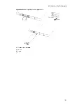
Figure 4-18
Attaching the power cable
(1) Cable clamp
(2) AC power cable
(3) AC power connector
Make sure to use the accessory power cable when the Switch is connected to 100
V AC. Other cable except the bundled one may cause a fire and/or an electric
shock.
In addition, use the accessory cable only for the Switch. Otherwise, a fire and/or an
electric shock may be the result.
Make sure to use a power cable specified by ALAXALA Networks Corporation when
the Switch is connected to 200 V AC. Otherwise, a fire or an electric shock might
result.
CAUTION
Prior to attaching or detaching the power cable, turn off the switch of relevant power
unit.
NOTE
For required specifications of power cables, see
2.3.2 Electrical power equipment
[Step 2]
Hold the power cable connector with the cable clamp.
Summary of Contents for AX2400S series
Page 3: ...Copyright Copyright C 2005 2011 ALAXALA Networks Corporation All rights reserved ...
Page 4: ......
Page 6: ...Preface II Find description from the AX2400S series manuals ...
Page 7: ...Preface III Find description from the AX3640S and AX3630S series manuals ...
Page 10: ...Preface VI ...
Page 14: ...Contents iv ...
Page 160: ...3 Preparation of Interface Cables and Terminals 130 ...


