


1. Components Overview
68
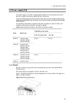
Figure 1-70
Front layout
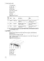
Figure 1-71
Back layout
Table 1-35
LED indications, switches and connectors
Nu
mb
er
Name
Type
Description
Details
(1)
POWER
Green LED
Indicates the power supply
status.
Lit in green: Powered-on. Electrical power is
output to the mounted power supply
modules.
Off: Input power failure to the EPU or
powered-off.
(2)
DC-OK
Green LED
Indicates the power output
status from the power
supply modules.
Lit in green: Normal output from the power
supply modules.
Off: Output power failure from the power
supply modules or powered-off.
(3)
DC-ALM
Red LED
Indicates the power output
status from the power
supply modules.
Lit in red: Output power failure from the
power supply modules.
Off: Normal output from the power supply
modules or powered-off.
(4)
EPU 1
Connector
Standby power connector 1
To output electrical power from the power
supply module mounted in slot 1.
Connect the standby power cable bundled
with the EPU to the standby power
connector on the back face of the switch.
(5)
EPU 2
Connector
Standby power connector 2
To output electrical power from the power
supply module mounted in slots 2 to 4.
Connect the standby power cable bundled
with the power supply module to the
standby power connector on the back face
of the switch.
(6)
EPU 3
Connector
Standby power connector 3
(7)
EPU 4
Connector
Standby power connector 4
Summary of Contents for AX2400S series
Page 3: ...Copyright Copyright C 2005 2011 ALAXALA Networks Corporation All rights reserved ...
Page 4: ......
Page 6: ...Preface II Find description from the AX2400S series manuals ...
Page 7: ...Preface III Find description from the AX3640S and AX3630S series manuals ...
Page 10: ...Preface VI ...
Page 14: ...Contents iv ...
Page 160: ...3 Preparation of Interface Cables and Terminals 130 ...


