


1. Components Overview
14
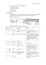
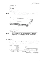
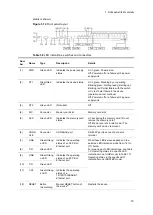
(1) External appearance
Figure 1-12
Front view
(1) CONSOLE port
(2) Memory card slot
(3) XFP slot
(4) SFP slot
(5) 10/100/1000BASE-T Ethernet port
(6) Security tape
NOTE
Do not peel away the security tape. If you do so,
will be displayed. The
device is no longer under warranty if
is displayed.
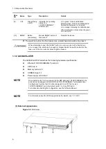
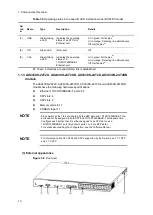
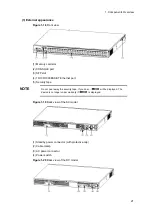
Figure 1-13
External appearance of the device
(1) Power supply unit slot 2
(2) Power supply unit slot 1
(3) Ground terminal
NOTE
To build a redundant power supply system, insert power supplies into both power
supply unit slots 1 and 2. Otherwise, insert a power supply unit into power supply
unit slot 1 and a fan unit into power supply unit slot 2.
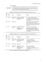
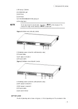
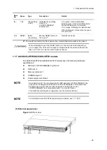
(2) Front panel
The front panel layout is shown in
Figure 1-14 Front panel layout
. The numbers in the
figure correspond to those in
Table 1-8 LED indications, switches and connectors
Note that the AX3640S-24T2XW model has a mode button to switch how the Ethernet port
Summary of Contents for AX2400S series
Page 3: ...Copyright Copyright C 2005 2011 ALAXALA Networks Corporation All rights reserved ...
Page 4: ......
Page 6: ...Preface II Find description from the AX2400S series manuals ...
Page 7: ...Preface III Find description from the AX3640S and AX3630S series manuals ...
Page 10: ...Preface VI ...
Page 14: ...Contents iv ...
Page 160: ...3 Preparation of Interface Cables and Terminals 130 ...


