background image


2


„

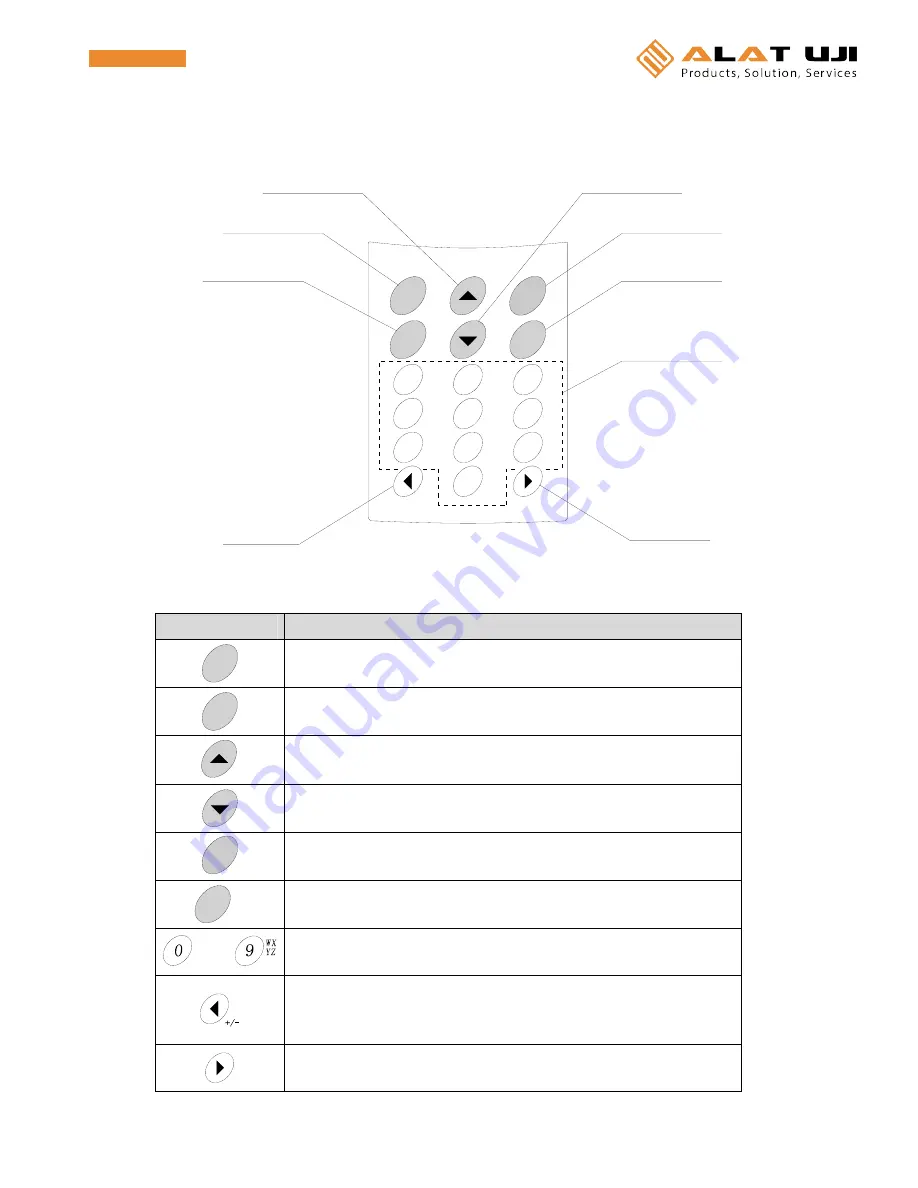
  Key names and functions 

[Key names] 


[Key functions] 

Key 

Function 

ENT


Setting and registration of the data and movement to the next screen 
Start of the recording operation 

Cancel
Stop


Cancellation of each item and return to the previous screen 
Stop of the recording operation 


Up movement of the cursor 
Backward movement of the recorded data in the successive order as checking data   


Down movement of the cursor   
Forward movement of the recorded data in the successive order as checking data   

Power


Turning(ON or OFF) of the power or display 

FUNC

Clear


Display of the main menu 
Clearance of the character at the cursor position as inputting characters 

SYMB

 to 


Input of a numeric value or character 
Change of the display mode (1, 2, 4) 


Left movement of the cursor 
Change of the display channel in the 1&2-channel display mode 
Change to “

“ input as inputting numeric values 


Right movement of the cursor 
Change of the display channel in the 1&2-channel display mode 

+/-

0

GH

4

7

ch

1

5

8

2

6

9

3

電源キー

右 キ ー

テ ン キ ー

機能キー

左 キ ー

戻 る キ ー

決 定 キ ー

ch

ch I

PQ
RS

上キー

下キー

Power

FUNC

Clear

ENT

Cancel
Stop

AB

C

JK

TU

MN

O

WX
YZ

DE

F

L

V

SYMB

Up key 

Enter key 

Cancel key 

Left key 

Down key 

Power key 

Function key 

Ten-key pad 

Right key 

Summary of Contents for OM-2041

Page 1: ...2 FUNC 6 9 3 ch 1 ch 2 ch 3 ch 4 ch ch I PQ RS AB C JK L TU V MN O WX YZ DE F OMEGA Cancel Stop ENT Power Clear SYM B Office Jl Radin Inten II No 62 Duren Sawit Jakarta 13440 Indonesia Workshop Jl Pahlawan Revolusi No 22B Jakarta 13430 Indonesia Phone 021 8690 6777 Hunting Fax 021 8690 6777 Mobile 62 816 1740 8925 Fax 021 8690 6771 ...

Page 2: ...l rights reserved Copyright reserved The contents of this manual are subject to change without prior notice Figures and illustrations stated in this manual may be emphasized simplified or omitted to describe the contents Contact your nearest sales representative if any unclear point incorrect description or missing description is found in the contents of this manual Microsoft and Windows are the t...

Page 3: ...ified measurement range not to cause the unit to malfunction or to be damaged z Never attempt to disassemble or modify this unit z Use always the parts specified by OMEGA ENGINEERING INC on the replacement of any parts or expendables z Do not put any foreign object in the sensor insertion port external power supply port or communication port Otherwise an electrical shock a fire or other damage to ...

Page 4: ...atic electricity or electromagnetic wave such as television set microwave oven or radio receiver as much as possible Otherwise malfunction or trouble may occur z Keep this unit away from any equipment producing the strong high frequency or surge as much as possible Otherwise malfunction or trouble may occur z Wipe it off lightly with a cloth which is wrung out with neutral detergent to clean this ...

Page 5: ...the probe to be damaged by the heated up grip z Use always the probe grip and the connection cable within the specified temperature range The heat resistance of such part is low in comparison with the measurement part of the probe metallic portion z The sheath thermocouple wire is intended for the fixed wiring Avoid the winding the twist the stretch friction and vibration for the wire repeatedly n...

Page 6: ... 18 Starting up Home Screen 20 Various settings 24 1 Checking the remaining memory battery capacities 26 2 ON OFF settings of the backlight sound 28 3 Setting of the auto power off 29 4 Setting of offset values 30 5 Adjustment of the LCD contrast 31 6 Setting of the date and time 32 7 Setting of an instrument name 33 8 Default setting of recording 34 9 Deletion of all logs tags 40 10 Initializatio...

Page 7: ... DC IN P C ch 1 ch 2 ch 3 ch 4 ch ch I PQ RS AB C JK L TU V MN O WX YZ DE F LOCK OMEGA Cancel Stop ENT Power Clear SYM B Handy Logger OM 2041 Don t put any other thing without specification into plugs Don t use this instrument as any cap opens Use only specified AC adaptor Don t drop and don t put impact on the instrument Exchange dry cells as the compartment is dry and fasten the lid tightly Plea...

Page 8: ...ning ON or OFF of the power or display FU NC C lear Display of the main menu Clearance of the character at the cursor position as inputting characters SYM B to Input of a numeric value or character Change of the display mode 1 2 4 Left movement of the cursor Change of the display channel in the 1 2 channel display mode Change to input as inputting numeric values Right movement of the cursor Change...

Page 9: ...s key to display Hereupon as pressing key repeatedly the display is alternately switched between and blank press key to move the cursor to the right to set or blank How to input alphanumeric characters The character is changed by the times of pressing ten key Times of pressing the key 1 time 2 times 3 times 4 times 5 times 6 times 7 times 8 times 9 times 10 times 1 A B C 2 a b c 2 D E F 3 d e f 3 ...

Page 10: ...rt of this unit to mount the battery cover h Turn the battery cover lock clockwise to lock it by a coin If the external power supply AC adaptor is not connected the unit starts immediately after replacing the batteries CAUTION Do not use any battery other than the specified one Otherwise the unit may malfunction If the battery cover is not closed completely the water may enter or the cover may be ...

Page 11: ...e specified one Otherwise the unit may malfunction Do not insert the AC adaptor into the communication port Otherwise the unit may malfunction Insert the plug of the AC adaptor into the port of this unit firmly until it is in contact with the far side Hold the plug firmly and pull it out as disconnecting the AC adaptor If the lead cable is pulled to disconnect the AC adaptor the unit may malfuncti...

Page 12: ... or sensor may be damaged and may malfunction Pay attention carefully enough not to peel off the connector packing when inserting the connector If the connector packing is peeled off the drip proof performance cannot be maintained and the unit may malfunction Connect or disconnect with the sensor carefully enough not to break any sensor lead Otherwise wiring trouble may occur and the unit may malf...

Page 13: ...the wire port g Tighten the terminal screw of the current voltage adaptor and close the wire port CAUTION The drip proof performance cannot be maintained while using the current voltage adaptor The following shows the lead wires which is suitable for the current voltage adaptor Solid wire 0 14 to 1 5mm2 Stranded wire 0 14 to 1mm2 AWG26 to16 Never loosen the case screw phillips screw 1 Case screw 1...

Page 14: ...the sensor carefully enough not to break any sensor lead Otherwise wiring trouble may occur and the unit may malfunction Disconnection with the sensor c Switch off this unit d Hold the sensor connector and pull it out straight CAUTION A general thermocouple connector on the market is available for the unit However note that the thermocouple connector different from the specified sensor is not appl...

Page 15: ...hers d Insert this unit from the top of the holder CAUTION The mounting holder installation conditions must conform to the storage conditions of this unit Install the mounting holder vertically Do not insert this unit reversely in the vertical or back and forth direction Mounting holder Screw hole 2 locations Attached screws and washers ...

Page 16: ...he batteries according to the section Mounting and replacement of the batteries g Disconnect the DC adaptor finally CAUTION Do not use any battery other than the specified one Otherwise the unit may malfunction Do not insert the DC adaptor to the communication port Otherwise the unit may malfunction Inset the plug of the DC adaptor into the port of this unit firmly until it is in contact with the ...

Page 17: ...If the lead cable is pulled to disconnect the connector the unit may malfunction USB port A connector Logger side Connect the mini B connector of the USB cable to the communication port Mini B connector Open the cover of the communication port with the PC marking and insert the plug of the USB cable firmly into the communication port until it is in contact with the far side Also use the special ca...

Page 18: ...unit d Open the cover of the port with the PC marking e Insert the plug of the special cable firmly until it is in contact with the far side f Switch on this unit CAUTION Use the special cable supplied with the software If any connection cable other than the specified one is used the unit may malfunction Insert the plug of the special cable firmly into the communication port of the unit until it i...

Page 19: ...ion standby screen Perform the operation via the software When the communication is started the message Communication will appear on the communicating screen Press CANCEL key to return from the communication standby screen to the previous screen See the instruction manual for software for further information on software operation Communicating ...

Page 20: ... message will appear Stop the operation and save the recorded data if this message screen appears Contact quickly your local sales representative or sales office to replace the built in backup battery charge CAUTION If the batteries four AA batteries are replaced with this message indicated the power is not supplied to this unit as soon as any battery is removed In this case therefore the power sh...

Page 21: ...location Setting item Contents c Log setting Interval Intervals to record the measured value Sensor type Type of the sensor to be connected to each channel Unit Unit of indication as using the voltage current input adaptor Minimum value of scale Indication at the minimum 0V 0mA by the voltage current input adaptor Maximum value of scale Indication at the maximum value 5V 20mA by the voltage curren...

Page 22: ...and eComment Setting location Setting item Contents c Tag setting Sensor type Type of the sensor to be connected to each channel Unit Unit of indication as using the voltage current input adaptor Minimum value of scale Indication at the minimum value 0V 0mA by the voltage current input adaptor Maximum value of scale Indication at the maximum value 5V 20mA by the voltage current input adaptor Input...

Page 23: ... confirmation screen of the recording mode Select Yes by the or key and then press ENT key When No is selected the operation is started up without changing of the mode Normal startup The operation is started up with the mode changed log mode to tag mode or tag mode to log mode The home screen will appear CAUTION When the mode is changed the recorded data and the setting in the previous mode are cl...

Page 24: ...Instrument name Auto power off LCD Contrast Accum base Alarm Interval D e f a u lt s e t t in g s S e n s o r t y p e All LOG delete LCD contrast All LOG delete Unit Scaling FUNC Memory Battery Initialize Memory Battery Initialize Instrument name Backlight Sound Temp shift Auto power off Clock settings Backlight Sound Temperature shift Clock Settings Default settings ENT D a t a c h e c k 1 2 4 c ...

Page 25: ...C ENT FUNC Remark select Delete settings FUNC POWER ON Other settings Other Settings Instrument name Auto power off LCD Contrast Alarm D e f a u lt s e t t in g s S e n s o r t y p e All TAG delete LCD contrast All TAG delete Unit Scaling FUNC Memory Battery Initialize Memory Battery Initialize Instrument name Backlight Sound Temp shift Auto power off Clock settings Backlight Sound Temperature shi...

Page 26: ... shown at the lower portion of the screen The home screen provides three kinds of display modes depending on the channel number to display on it This display mode can be changed by the one touch operation Change the display channel by the or key in the 1 channel and 2 channel display modes Key 1 channel display 2 channel display CH1 CH2 CH3 CH4 CH1 CH1 CH4 CH3 CH2 CH1 CH1 2 CH3 4 CH1 2 メモリ残量 現在値 入...

Page 27: ...00 all of four channels are used and data is recorded at intervals of 5 min the available recording time is 1250 min 1000 free memory capacity 4ch number of channels in use 5 min recording interval 1250 min z Tag mode In the tag mode the data can be recorded until the total number of data recorded to 20 tags reaches 10000 One number of data corresponds to the data volume used for one recording at ...

Page 28: ...t to 0 mA of the input calculated Indication span of this unit output span of the input 4mA Voltage Indication at 5Vof the input Max scale 9999 to 9999 Current Indication at 20mA of the input Fraction part 0 to 3 Number of digits below decimal point 0 0 1 0 0 2 0 00 3 0 000 CAUTION If no connection is set for all channels the data cannot be recorded Icon indication Icons are indicated at the upper...

Page 29: ...n at the same time to cancel the key lock f Data mark In the log mode the mark is able to be put on the recorded data The data mark icon is lit when the mark is put on the recorded data or the marked data is shown on the data check screen Check of remaining capacity unit name When pressing the key while the home screen is being displayed the battery level and instrument name can be checked Press C...

Page 30: ... settings 1 Display the home screen 2 Press Clear FUNC key The screen is changed to the main menu screen Select Other settings by the or key 3 Press ENT key The screen is changed to the screen of other settings メモリ残量 現在値 ログ番号 現在日時 Log No Available of memory capacity Current value Current date and time ...

Page 31: ... key and alarm buzzer Auto power off Setting of waiting time for the auto power off Temp shift Setting of offset for measured data LCD contrast Adjustment of the contrast of LCD panel Clock settings Setting of date and time Instrument name Setting of unit name up to eight characters Default settings The default settings of recording or the deletion All LOG delete Simultaneous deletion of all log s...

Page 32: ...to the data volume used for one recording at one channel Therefore the number of data to be recorded may vary depending on the number of channels to be used The available recording cycles is calculated from the following formula Available recording cycles cycles Free memory capacity data Number of channels in use ch The available recording time is calculated from the following formula Available re...

Page 33: ...g cycles Free memory capacity data 11 11 2 Available recording cycles Free memory capacity data 11 14 3 Available recording cycles Free memory capacity data 11 17 4 Available recording cycles Free memory capacity data 11 20 Example If the free remainder of memory capacity is 1000 and the data is recorded using three channels up to 647 data records can be recorded 1000 free memory capacity 11 17 co...

Page 34: ...et Select a setting item from various setting items by the or key and change the ON OFF setting by the or key When the unit is operated by the batteries it is recommended to set all items to OFF in order to extend the battery service life Item ON OFF Backlight Lighting up of the backlight as turning ON of the display Non backlight Key sound A beep sound as pressing a key Non beep sound Alarm Conti...

Page 35: ...r settings and press ENT key 3 3 Select Auto power off and press ENT key Select a period of time by the or key In addition to 1 min 5 min and 10 min settings the continuous operation mode is provided in which the auto power off is not activated Keep the POWER key pressed for 3 sec or longer to power OFF the unit regardless of any setting Press CANCEL key to return to the previous screen CAUTION Th...

Page 36: ...teps of 0 1 C within a range of 20 C Select a desired channel by the or key and then input a numeric value by the ten key pad or the or key The adjusted current data is shown in on the right Press CANCEL key to return to the previous screen 4 4 Press ENT key to set the settings CAUTION This offset affects the recording data or display data only when the input signal type is K T E or J However the ...

Page 37: ...NC key 5 2 Select Other settings and press ENT key 5 3 Select LCD contrast and press ENT key The screen contrast can be changed by the or key Adjust the contrast in proper conditions Press CANCEL key to return to the previous screen CAUTION If the contrast is set to a low level the screen becomes difficult to read 5 4 Press ENT key to set the settings ...

Page 38: ... the ten key pad or the or key The date and time are set with 2 digit numeric value as shown in the following example Input example Date 0 2 0 3 1 2 Time 1 2 3 4 5 6 Press CANCEL key to return to the previous screen CAUTION If any invalid date and or time are input they are corrected automatically Therefore press ENT key after checking the date and time to input 6 4 Press ENT key to set the settin...

Page 39: ...en and press Clear FUNC key 7 2 Select Other settings and press ENT key 7 3 Select Instrument name and press ENT key Input an instrument name by the ten key pad or the or key The name up to eight characters can be input Press CANCEL key to return to the previous screen 7 4 Press ENT key to set the settings 英字 カナ切替え表示 機器名称 Instrument name Character input ...

Page 40: ...tting screen of sensor type Log mode Tag mode In this unit the K T E or J type thermocouple are available Additionally when using the optional voltage input adaptor or current input adaptor sold separately it is available for DC voltage 0 to 5V or DC current 0 to 20 mA signals Move the cursor to a channel to set by the or key and change the input type by the or key Symbol K T E J V Input type K th...

Page 41: ...d to 1 min when it is from 1 min to 24 hrs Press CANCEL key to return to the previous screen CAUTION If any interval beyond setting range is input this interval is not set even though ENT key is pressed and then it is automatically corrected to an acceptable setting value Therefore press ENT key after checking or correcting the value to input This setting is not provided in the tag mode ログ番号 インターバ...

Page 42: ...ng recording data Move the cursor to a channel and the upper lower limit by the or key Then set an alarm temperature by the or key or the ten key pad The settable temperature may vary depending on the input type Input type Alarm setting range K 200 0 to 1370 0 C T 200 0 to 400 0 C E 200 0 to 700 0 C J 200 0 to 700 0 C Press CANCEL key to return to the previous screen CAUTION The setting is not ava...

Page 43: ...rence temperature for accumulation by the or key Then set the reference temperature by the or key or the ten key pad The settable temperature may vary depending on the input type Input type setting range of reference temperature for accumulation K 200 0 to 1370 0 C T 200 0 to 400 0 C E 200 0 to 700 0 C J 200 0 to 700 0 C To return to the previous screen press CANCEL key CAUTION The setting is not ...

Page 44: ... writing CAUTION The confirmation screen of writing cannot be returned to the previous screen even though CANCEL key is pressed 8 8Press ENT key to register each setting as the default The screen is returned to the home screen CAUTION Move the cursor to No by the or key and press ENT key The screen is then returned to the screen of log tag selection without changing of settings Log No ...

Page 45: ...A of the input calculated Indication span of this unit output span of the input 4mA Voltage Indication at 5V of the input Max scale 9999 to 9999 Current Indication at 20mA of the input Fraction part 0 to 3 Number of digits below decimal point 0 0 1 0 0 2 0 00 3 0 000 Scaling For example when connecting a unit having an external output of 4 to 20 mA using an indication scale of 0 0 to 100 0 rh make...

Page 46: ...by the or key on the confirmation screen of deletion Press CANCEL key to return to the previous screen 9 4 Press ENT key to delete all logs CAUTION When this operation is run all of recorded setting and data are deleted completely Before running this operation read the data and save it into a file When No is selected on the confirmation screen of deletion and ENT key is pressed the screen is retur...

Page 47: ...ize and press ENT key Move the cursor to Yes by the or key on the confirmation screen of initialization Press CANCEL key to return to the previous screen 10 4 Press ENT key to initialize the settings CAUTION When this operation is run all of recorded setting and data are deleted completely Before running this operation read the data and save it into a file When No is selected on the confirmation s...

Page 48: ...by the or key on the screen of switching temperature unit Press CANCEL key to return to the previous screen 11 4 Press ENT key to switch the unit CAUTION When this operation is run all of recorded setting and data are deleted completely Before running this operation read the data and save it into a file When No is selected on the deletion confirmation screen and ENT key is pressed the screen is re...

Page 49: ...e Please refer to Recording of personnel and comment p 41 of an Operation Manual to select a personnel name and the comment 1 Display the home screen 2 Press Clear FUNC key The screen is changed to the main menu screen Select Personnel Remark by the or key 3 Press ENT key The screen is changed to the selection screen of personnel remark On this screen a working person and comment can be set select...

Page 50: ...t characters by the ten key pad or the or key Up to 8 alphanumeric characters can be used Press CANCEL key to return to the previous screen 1 5 Press ENT key to register each name of personnel The screen is changed to the selection screen of personnel CAUTION At this time the name of working person is only registered without select Select the name of personnel in the same manner as described for s...

Page 51: ...Clear FUNC key Input characters by the ten key pad or the or key Up to 8 alphanumeric characters can be used Press CANCEL key to return to the previous screen 2 5 Press ENT key to register a comment The screen is changed to the selection screen of comment CAUTION At this time the comment is only registered without selection Select the comment in the same manner as described for selection of commen...

Page 52: ...e type correctly For details see 5 Settings of the recording Operation manual The offset value is changed Change the offset value For details see various settings 4 Setting offset values The temperature is measured in error The sensor is faulty Replace the sensor with a new one The strong static electricity electromagnetic wave or high frequency may adversely affect the unit Do not put this unit o...

Page 53: ...or software The display goes out The auto power off is activated Make the auto power off inactive For details see Various settings 3 Setting the auto power off function The display is dark The LCD contrast is low Adjust the LCD contrast For details see Various settings 5 Adjusting the LCD contrast The message Need to change a backup battery is shown The backup battery runs out Contact your local s...

Page 54: ... C at an ambient temperature of 15 to 35 C 0 7 C at an ambient temperature of 10 to 15 C or 35 to 50 C Accuracy is specified under an ambient temperature variation of 2 C or less Temperature coefficient 0 01 C of measuring range specified with an ambient temperature variation of 2 C or less Allowable signal source resistance 100Ω or less burnout detectable Input resistance 1MΩ or less at DC voltag...

Page 55: ...1 Instruction manual Operation 1 Battery replacement adaptor DC adaptor 1 Optional units sold separately AC adaptor OM AC INPUT 100 240V 50 60Hz 0 5A OUTPUT DC9V 2A 18W Data read Software OM SPN C2 RS 232C or OM SPN USB USB Applicable personal computer model IBM PC AT compatibles Applicable OS Windows98 Me WindowsNT4 0 Windows2000 and WindowsXP Functions Read Write Save of recording setting CSV fo...

Reviews: