background image

OG-X-FR openGear Frame v1.0r1 22 www.aja.com


Chapter 7 – MFC-8322-S Network Card

Overview

AJA's OG-X-FR openGear frame ships with the MFC-8322-S network card pre-

installed.

MFC-8322-S Network Card Features

•  Compatible with the OG-X-FR series frames 
•  Compatible with the OG-3-FR series frames 
•  Monitors frame power usage, the inlet ambient temperature, the airflow 

requirements of high-powered cards, and sets the fan speed accordingly

NOTE:  Higher power consumption requires higher fan speed for adequate cooling. The 

fans always run at maximum speed for five seconds after the fan door is closed, 

then adjusts to the appropriate level based on power consumption and the inlet 

ambient temperature.

•  Monitors the frame door and each frame power supply
•  Monitors the fan door and notifies the user if the door is left open too long
•  Monitors the status of other cards in the frame via the internal bus
•  Generates alarms if any of the monitored functions develop errors
•  Network settings storage location on the GFC-8322 Reference card that saves 

items configured on the Network tab plus the Frame Name

•  Provides external 10/100Mbps Ethernet connectivity to communicate with 

DashBoard

User Interfaces

Your Network Controller Card may include the following interfaces.

DashBoard Control System

The DashBoard Control System enables you to monitor and control openGear 

frames and cards from a computer. DashBoard communicates with other cards 

in the openGear frames through the Network Controller Cards. The DashBoard 

software and user manual are available for download from the Ross website.

Card-edge Controls

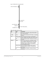
The front-edge of the Network Controller Card feature LED indicators for the 

power, Ethernet connection, and general communication activity. The Network 

Controller Card also include DIP switches for specifying the IP address of the 

frame.

Summary of Contents for OG-X-FR

Page 1: ...OG X FR openGear Frame Version 1 0r1 Published July 30 2018 Installation and Operation Guide ...

Page 2: ... V2Digital are trademarks of AJA Video Systems Inc All other trademarks are the property of their respective owners Copyright Copyright 2018 AJA Video Systems Inc All rights reserved All information in this manual is subject to change without notice No part of the document may be reproduced or transmitted in any form or by any means electronic or mechanical including photocopying or recording with...

Page 3: ...rflow Requirements 14 Installation Requirements 14 Installing the Rear Support Bars and Brackets 14 Installing the FSB OGX 15 Connecting to a Power Supply 16 Chapter 5 Ethernet Cabling 18 Cabling the Ethernet Port on the OG X FR Frame 18 Required Pinouts 18 Connecting to a Network 18 Chapter 6 Reference Cabling 20 GFC 8322 Overview 20 Connecting a Video Reference Source 20 Connecting to a Referenc...

Page 4: ...Feature 34 Manually Adding OG X FR Frames to DashBoard 34 Re naming the OG X FR Frame in the Tree View 35 Removing an OG X FR Frame from the Tree View in DashBoard 36 Auto Discovery 37 Using DashBoard to Access openGear Cards in the OG X FR Frame 37 Chapter 9 Maintenance 39 Installing a Frame Power Supply 39 Fan Filter Maintenance 39 Cleaning the Frame Air Filter 39 Replacing the Frame Air Filter ...

Page 5: ... features and displaying the OG X FR in DashBoard Maintenance provides instructions for cleaning the fan filter and replacing a failed Cooling Fan Module Technical Specifications provides the specifications for the OG X FR Service Information provides information on the warranty and repair policy for your OG X FR Glossary provides a list of terms used throughout this guide Related Publications It ...

Page 6: ... of referenced guides manuals or documents For example For more information refer to the DashBoard User Manual Menu Sequences Menu arrows are used in procedures to identify a sequence of menu items that you must follow For example if a step reads File Save As you would click the File menu and then click Save As ...

Page 7: ... any mix of analog digital video and audio cards in the same frame Available with individual card specific modules for connector flexibility Optional redundant power supply is hot swappable for 24 7 operation Power switch is accessible from front of the rack frame Power supplies are replaceable from the front of the frame without requiring rear frame access Separate power cords to each supply for ...

Page 8: ...oard Gigabit Ethernet switch with GigE access to each of the 20 processing card slots NOTE Gigabit Ethernet is only available with the MFC OG3 N installed in the OG X FR frame Figure 1 Workflow of the OG X FR PS2 PS1 ETHERNET SLOT 20 SLOT 17 SLOT 13 SLOT 9 SLOT 5 SLOT 4 SLOT 1 FAN CTRL REF 1 REF 2 12V 7 5V REF 1 REF 1 REF 2 1 F EF RE R 2 2 F EF RE R GFC 8322 SLOT 2 SLOT 3 SLOT 6 SLOT 7 SLOT 8 SLOT...

Page 9: ...the frame The Diagnostic Panel organizes the messages starting with the most recent at the top of the list Refer to the user guide for your openGear card to learn more about the types of error conditions that your card reports 2 Toggle Button The Toggle button is located directly to the left of the Diagnostic Panel and enables you to mute the audio alarm or quickly scroll through the error message...

Page 10: ...ew on page 20 for more information 3 Card Slots There are a total of 20 card slots in the OG X FR chassis and are used to install openGear cards into the chassis Depending on the card model and rear module you are using multiple slots may be required Refer to the user guide for your openGear card for installation details for your card 4 Controller Card There are two models of Controller Card MFC 8...

Page 11: ... accept two independent reference signals supporting the following reference signal types Analog black Tri level sync and AES DARS reference 5 Rear Modules for openGear Cards The OG X FR frame supports module dependent rear modules Rear modules can be ordered with cards and are easy and quick to install Blank plates must be installed if the slots are not populated with openGear cards and rear modu...

Page 12: ...nGear card is installed in the correct slot in the OG X FR frame Up to 10 cards can be installed in a frame when using these modules Split Rear Modules Much like the modules for the OG3 FR frames split modules for the OG X FR frame features two card connectors and can have a combination of BNC WECO fiber optic serial and ethernet connectors Each card connector is routed to a column of five BNCs A ...

Page 13: ...mation on installing the brackets refer to the section Installing the Rear Support Bars and Brackets on page 14 the frame dimensions refer to Specifications on page 44 Static Discharge Throughout this chapter please heed the following cautionary note ESD Susceptibility Static discharge can cause serious damage to sensitive semiconductor devices Avoid handling circuit boards in high static environm...

Page 14: ...rame must also be maintained Ensure to adhere to the following clearance recommendations Minimum 2 5 08cm clearance both right and left hand side of the chassis sides with unrestricted vertical airflow Minimum 5 12 7cm clearance at the chassis rear with unrestricted vertical airflow Installation Requirements Keep the following in mind when installing your OG X FR frame Install the frame for maximu...

Page 15: ...K OF SHOCK DO NOT OPEN OGX FR 2 Install the Rail Guides for each Rack Mount Arm INPUTS 1 2 3 4 5 PSL GPIO TAL LY PS 2 PS 1 LTC 6 7 Rail Guide Retaining Bolts Rack Mount Arm PS2 ETH ERNET 100 240V 47 63Hz 450W CAUTION RISK OF SHOCK DO NOT OPEN REF 1 LOO P REF 2 LOO P PS1 100 240V 50 60Hz 600W CAUTION RISK OF SHOCK DO NOT OPEN 3 Secure the Rail Guides and Rack Mount Arms to the rack INPUTS 1 2 3 4 5...

Page 16: ...life span of the connectors Power Supply Connectors PSU1 PSU2 There are two power supply connectors located on the back of the OG X FR PSU1 This connector is designated as the AC Connector for the first power supply PSU2 This connector is designated as the AC Connector for the second power supply Where the connectors are located is dependent on the frame you are using For More Information on power...

Page 17: ...lug the second IEC connector into PS 2 36 9a 87 21 5 6 2 6 2 2 127 23 1 5 223 5 223 36 7 51 7 9a 87 21 5 6 2 6 2 2 127 23 1 2 5 7R 5HGXQGDQW 3RZHU 6XSSO 7R 0DLQ 3RZHU 6XSSO NOTE Each AC connector includes a PowerLock which is designed to retain the power cable connector 3 Clip the PowerLock over the shoulder of the inserted AC cable end 4 Connect the supplied power cable s three prong male connect...

Page 18: ... is a standard 10 100 1000 RJ45 Ethernet connector and is used to exchange information with an external monitoring or control system over an ethernet network You must have the MFC OG3 N installed in the OG X FR to take advantage of the Gigabit ethernet connectivity available for cards in the OG X FR frame Required Pinouts The Ethernet port has its RJ45 connector wired as a Network Interface Card N...

Page 19: ...at has a route to the network your DashBoard client computer is on 1 Connect one free end of a straight through CAT5 5e 6 cable to a free port of the network hub 2 Connect the other end of the same cable to the Ethernet port on the OG X FR rear panel Figure 5 OG X FR Frame Ethernet Cabling 36 9a 87 21 5 6 2 6 2 2 127 23 1 5 223 5 223 36 7 51 7 9a 87 21 5 6 2 6 2 2 127 23 1 7R WKHUQHW 1HWZRUN 2 5 ...

Page 20: ...e of taking the signal from one of the card BNCs This provides for ease of installation and reduction in reference cabling requirements Connecting to a Reference Source If only one reference type is required for the OG X FR frame connect it to the REF 1 BNC Two reference types enables you to use reference sources with a different signal formats each via a separate REF BNC For More Information on o...

Page 21: ...deo referencing loop has a 75ohm termination connected to its REF 2 IN BNC Troubleshooting During normal operation the GFC 8322 must never be removed from the OG X FR frame To ensure this the metal retaining latch located on the front of the GFC 8322 must be engaged pushed down to prevent accidental removal of the GFC 8322 from its slot Verify that the GFC 8322 is properly seated in its slot and t...

Page 22: ...o long Monitors the status of other cards in the frame via the internal bus Generates alarms if any of the monitored functions develop errors Network settings storage location on the GFC 8322 Reference card that saves items configured on the Network tab plus the Frame Name Provides external 10 100Mbps Ethernet connectivity to communicate with DashBoard User Interfaces Your Network Controller Card ...

Page 23: ...Network Controller Card This section outlines how to install an Network Controller Card in an openGear frame The same procedure applies regardless of the frame or card type The Network Controller Card installs in the last slot on the right side of the openGear frame when facing the frame CAUTION You must install the MFC 8322 S into an OG 3 FR or OG X FR frame Attempting to install this card in ano...

Page 24: ...tion using DIP switch es The Network Controller card can be forced to use specific pre defined network settings by means of DIP switches located on the card surface This can be used to establish initial communications when no DHCP server is available or to override a custom user configuration Custom user configuration via DashBoard Using the network setting options available in the DashBoard Contr...

Page 25: ...eset network configuration using the DIP Switch es 1 Power down the openGear frame that houses the Network Controller card 2 Quit DashBoard on your computer 3 Set the DIP Switch to specify the preset IP Address as outlined in the applicable Setup chapter of this manual for your Network Controller card model 4 Ensure the network settings of your computer are compatible with those chosen for the Net...

Page 26: ...s is the Subnet Mask address for your LAN Default Gateway This is the IP Address for connection outside the subnet 7 To save the new settings click Apply in the Network tab The settings are saved immediately and take effect except when overridden by DIP Switch settings Clicking Cancel reverts to the previous settings User Rights Management If your facility has installed and configured the DashBoar...

Page 27: ...recover a lost Master Password The user specified password is temporarily ignored and the default value of password is used To configure the Master Password in DashBoard 1 Navigate to the frame in the Tree View of the DashBoard client 2 Right click the frame node and select Lock Unlock Access to display the Change Master Password dialog By default the current Master Password for the frame is autom...

Page 28: ...elect one of the following methods Click Try Password to connect to the selected frame or Click Try for All to connect to all locked frames displayed in the Tree View Only when you attempt to connect to additional locked frames and the login fails are you prompted for the password 6 If the password was incorrect an error message displays to prompt you for another log in attempt Software Upgrades Y...

Page 29: ...m dialog displays indicating the number of cards that will reboot Click Yes to continue the upgrade process Note that clicking Cancel or No returns you to the Uploading to Selected Devices dialog without rebooting the card s NOTE The communications processor of the Network Controller Card requires approximately 30 seconds to re start and re establish network communications The card s are temporari...

Page 30: ...mper into Position 2 3 3 DIP Switches SW1 and SW2 are used in conjunction with the DashBoard menus to set the IP Address of the MFC 8322 S SW3 is used to override the Master Password for the MFC 8322 S This password limits access to the card and the cards installed in the frame 4 Card Lock This lock located near the front edge of the card is used to secure the card in its frame slot Configuring th...

Page 31: ...Using a Master Password on page 26 for details OFF This is the recommended position A user specified Master Password is used The default password is password It can be changed using DashBoard as outlined in the section Using a Master Password on page 2 7 ON This position is used to recover a lost Master Password The user specified password is temporarily ignored and the default value of password i...

Page 32: ...with the other cards within the frame Off When off this LED indicates an absence of incoming messages Ethernet Yellow When lit this LED indicates a valid Ethernet link has been established No data transfer is currently taking place NOTE If this LED remains lit for an extended period of time e g minutes or more ensure that the Ethernet port on the frame is connected to a functioning Ethernet switch...

Page 33: ...ne that is verified to work 3 Input Signal Status Verify that source equipment is operating correctly and that a valid signal is being supplied 4 Output Signal Path Verify that destination equipment is operating correctly and receiving a valid signal 5 Card Exchange Exchanging a suspect card with a card that is known to be working correctly is an efficient method for localizing problems to individ...

Page 34: ...has a physical wired ethernet connection Wireless connections do not allow device discovery For More Information on downloading and installing the DashBoard client software refer to the DashBoard User Manual To launch DashBoard 1 Ensure that DashBoard is installed on a PC connected to the same network as your OG X FR frame 2 Ensure that you are running the latest DashBoard software 3 Launch DashBo...

Page 35: ...2 From the Protocol options select OGP openGear Protocol 3 Use the Port field to specify the port used for communication 4 Select the Remember connection settings for this frame box to retain the settings 5 Click Finish to display the OG X FR frame in the Tree View NOTE OG X FR frames added to the Tree View are also displayed in the Advanced Tree View 6 Repeat the procedure for each OG X FR frame ...

Page 36: ...FR frame from a Tree View in DashBoard Once a frame is removed DashBoard no longer reports the status in the Tree View and you are no longer able to monitor or control the affected devices If communication with a frame is disconnected via the Disconnect option the status indicator is light gray until the frame is re connected If the status indicator is dark gray with the rest of the node displayin...

Page 37: ...iscovery feature NOTE You can still disconnect from an auto discovered frame by toggling the Automatic Discovery option off Using DashBoard to Access openGear Cards in the OG X FR Frame The OG X FR frame displays in DashBoard as a main node in the Tree View with a series of sub nodes Each sub node represents an openGear card installed in that frame For More Information on available menus and param...

Page 38: ...aja com 4 If your openGear card has multiple interfaces A Expand the openGear card node B Double click a sub node to display that interface in the DashBoard window In the example below the Configuration interface for an MC1 MK is displayed ...

Page 39: ...frame 3 Push the power supply in firmly to ensure a tight connection at the rear of the frame Fan Filter Maintenance Routine maintenance of the fan filter installed in the OG X FR is highly recommended to ensure proper airflow through the chassis Cleaning the Frame Air Filter The OG X FR has a single air filter that is used to prevent dust and airborne particulates from contaminating the frame Thi...

Page 40: ...roperly in the cutouts on the frame door bracket 4 Using a Phillips screwdriver secure the faceplate using the four screws removed during step 2 of the procedure To remove the air filter from the frame door Replacing the Frame Air Filter Order the Air Filter Replacement Kit AFK OGX from your openGear sales representative before replacing the frame air filter in your OG X FR frame To remove the old...

Page 41: ...or The CFM OGX includes the fan board and filter pre installed in a new OG X FR frame door You will need to remove the old door from your OG X FR frame and replace it with the new door To remove the old door from the OG X FR frame 1 Gently pull the side door tabs towards the center of the door releasing the door from the frame NOTE The door extender arms retain the door to the chassis 2 Using both...

Page 42: ...d peripheral equipment for signs of trouble 2 Power Check Inspect the power indicator LED on the distribution frame front panel for the presence of power If the power LED is not illuminated verify that the power cable is connected to a power source and that power is available at the power main Confirm that the power supplies are fully seated in their slots If the power LED is still not illuminated...

Page 43: ...on base Network Controller Card the MFC OG3 N and any available options unless otherwise noted NTSC captions the CEA 608 D Line 21 Data Services captions openGear frame refers to the OG X FR frames unless otherwise noted PAL PAL B and PAL G unless otherwise stated PCR program clock reference PID packet identifier Production aperture the image lattice that represents the maximum possible image exte...

Page 44: ...High Density Split Rear Module 15W per card accommodates two openGear cards and requires two slots in the frame chassis Standard Rear Module Accommodates one openGear card and requires two slots in the frame chassis 30W per card or 45W if the openGear card has integrated cooling Double Wide Rear Module 60W per card or 75W for a single card with integrated cooling or 90W for a multi slot assembly w...

Page 45: ...g two conditions 1 This device may not cause harmful interference and 2 this device must accept any interference received including interference that may cause undesired operation Canadian ICES Statement Canadian Department of Communications Radio Interference Regulations This digital apparatus does not exceed the Class A limits for radio noise emissions from a digital apparatus as set out in the ...

Page 46: ...cause radio interference in which case the user may be required to take appropriate measures Achtung Dieses ist ein Gerät der Funkstörgrenzwertklasse A In Wohnbereichen können bei Betrieb dieses Gerätes Rundfunkstörungen auftreten in welchen Fällen der Benutzer für entsprechende Gegenmaßnahmen verantwortlich ist Attention Ceci est un produit de Classe A Dans un environnement domestique ce produit ...

Page 47: ...product based on the standard of the Bureau of Standards Metrology and Inspection BSMI CNS 13438 Class A In a domestic environment this product may cause radio interference in which case the user may be required to take adequate measures Japan Compliance Statement This is a Class A product based on the standard of the VCCI Council VCCI 32 2016 If this equipment is used in a domestic environment ra...

Page 48: ...nstall in accordance with the manufacturer s instructions Avertissement Ne bloquez aucune ouverture de ventilation Suivez les instructions du fabricant lors de l installation Warnung Die Lüftungsöffnungen dürfen nicht blockiert werden Nur gemäß den Anweisungen des Herstellers installieren Advertencia No bloquee ninguna de las aberturas de la ventilación Instale de acuerdo con las instrucciones del...

Page 49: ...ve para la conexión a tierra La expiga ancha o la tercera espiga sirven para su seguridad Si el enchufe suministrado no encaja en el tomacorriente consulte con un electricista para reemplazar el tomacorriente obsoleto Aviso Não anule a finalidade da segurança da ficha polarizada ou do tipo ligação terra Uma ficha polarizada tem duas lâminas sendo uma mais larga do que a outra Uma ficha do tipo de ...

Page 50: ...omprimido particularmente nas fichas em tomadas de parede de conveniência e no ponto de onde sai do dispositivo Avviso Proteggere il cavo di alimentazione in modo che nessuno ci cammini sopra e che non venga schiacciato soprattutto in corrispondenza delle spine e del punto in cui esce dal dispositivo Warning Unplug this device during lightning storms or when unused for long periods of time Avertis...

Page 51: ...ra danificado a quando foi derramado líquido ou caíram objectos sobre o dispositivo quando o dispositivo foi exposto à chuva ou à humidade quando não funciona normalmente ou quando foi deixado cair Avviso Fare riferimento al personale qualificato per tutti gli interventi di assistenza L assistenza è necessaria quando il dispositivo è stato danneggiato in qualche modo ad esempio se il cavo di alime...

Page 52: ...ttore Hazard High Voltage This situation or condition can cause injury due to electric shock Avertissement Tension élevée Cette situation ou condition peut causer des blessures dues à un choc électrique Warnung Hochspannung Diese Situation oder Bedingung kann zu Verletzungen durch Stromschlag führen Advertencia Alto voltaje Esta situación o condición puede causar lesiones debidas a una descarga el...

Page 53: ... this To reduce the risk of electrical shock disconnect both power cords before servicing equipment Avertissement Avis concernant la double alimentation électrique à lire soigneusement Pour éviter tout risque d électrocution débranchez les deux câbles électriques avant d intervenir sur l équipement Achtung Hinweis auf Doppel Netzkabel bitte lesen Um das Risiko eines Elektroschocks zu verringern mü...

Page 54: ...enzione tale conduttore deve essere collegato a un punto al potenziale di terra Advertencia de voltajes peligrosos El funcionamiento seguro de este producto require que se proporcione una conexión terrestre protegida Esta protección terrestre es proporcionada por el conductor de conexión en la tierra del cable de alimentación del equipo Para reducir el riesgo de descarga eléctrica al operador y el...

Page 55: ... improper use handling or maintenance Without limiting the foregoing AJA Video shall not be obligated to furnish service under this warranty or repair any damage or malfunction a resulting from attempts by personnel other than AJA Video representatives to install repair or service the product b resulting from improper use or connection to incompatible equipment c caused by the use of non AJA Video...

Page 56: ...S DO NOT ALLOW THE LIMITATION OF LIABILITY FOR PERSONAL INJURY OR OF INCIDENTAL OR CONSEQUENTIAL DAMAGES SO SOME OR ALL OF THE TERMS OF THIS PARAGRAPH MAY NOT APPLY TO YOU Governing Law and Language Your Rights This limited warranty is the only warranty provided by AJA Video on the hardware product It supersedes all prior or contemporaneous understandings regarding such subject matter No amendment...

Reviews: