Issue Date: 29 Jan 2009 Rev 1
Page 9
Section 5
ASSEMBLY PROCEDURE
The wing can be assembled in two positions, either lying flat or standing on the control frame.
Assembling the Sting 3 on the control frame is the most popular method of assembly in light winds.
This method is preferable as the sail is less prone to being soiled or damaged during assembly. In
higher winds it is preferable to lay the glider flat for assembly with the nose into the wind until ready
to launch.
Our suggested sequence is as follows:
Note: If resistance is encountered during any phase of set up or break down procedure stop
and investigate.
•
UNZIP THE BAG. Lay the wing down with zip up and the nose facing approximately 120
degrees from the wind direction. The nose should be facing into the wind when assembling
flat. Unzip the bag and unclip centre ties. Remove the bag of battens.
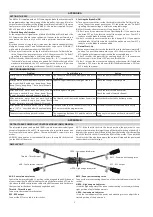
•
ASSEMBLE CONTROL FRAME. Spread the downtubes out. Connect the base bar using the
pip pins, inserting them from front to rear. When a pip pin is secured correctly it passes
completely through the downtube and base bar. Check that all the rigging wires are outside
the control frame. Route the VG cord if necessary.
•
STAND GLIDER UP. Rotate the control frame to the vertical position and rotate the wing 180
degrees so that it is sitting on the base bar. If assembling flat ensure that control bar is central
and the wires are not tangled.
•
REMOVE BAG. Remove the glider bag and unclip all of the ties.
•
SPREAD LEADING EDGES. Carefully spread both leading edges out half way then spread
leading edges to their approximate flying position.
IT IS ESSENTIAL THAT THE KEEL AND THE LEADING EDGES ARE KEPT IN THE SAME
PLANE OR DAMAGE WILL RESULT.
•
RAISE KING POST. Raise the kingpost and attach the reflex bridles.
Summary of Contents for Sting 3
Page 2: ...PART 108841 THIS PAGE LEFT BLANK INTENTIONALLY...
Page 30: ...Issue Date 29 Jan 2009 Rev 1 Page 30 THIS PAGE LEFT BLANK INTENTIONALLY...
Page 34: ...Issue Date 29 Jan 2009 Rev 1 Page 34 STING X BAR LEADING EDGE JUNCTION A4 4716...
Page 37: ...Issue Date 29 Jan 2009 Rev 1 Page 37 REAR LEADING EDGE ASSEMBLY STING A4 6859...
Page 38: ...Issue Date 29 Jan 2009 Rev 1 Page 38 STING III 154 NOSE JUNCTION ASSEMBLY A4 4717...
Page 40: ...Issue Date 29 Jan 2009 Rev 1 Page 40 STING III 168 NOSE JUNCTION ASSEMBLY A4 7743...
Page 42: ...Issue Date 29 Jan 2009 Rev 1 Page 42 STING III KEEL ASSEMBLY A4 7608...
Page 45: ...Issue Date 29 Jan 2009 Rev 1 Page 45 CONTROL FRAME STING III 154 PREASM A4 7625...
Page 47: ...Issue Date 29 Jan 2009 Rev 1 Page 47 CONTROL FRAME STING III 168 PREASM A4 7747...
Page 49: ...Issue Date 29 Jan 2009 Rev 1 Page 49 STING HANG LOOP ASSEMBLY A4 4796...
Page 50: ...Issue Date 29 Jan 2009 Rev 1 Page 50 STING III SAIL TO AIRFRAME ASSEMBLY A4 7748...
Page 53: ...Issue Date 29 Jan 2009 Rev 1 Page 53 STING III INTERCHANGE TABLE A4 7749...
Page 54: ...Issue Date 29 Jan 2009 Rev 1 Page 54 THIS PAGE LEFT BLANK INTENTIONALLY...