background image

USE OM - JANUARY 2017


30 

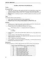
APPENDIX D: 

COMPLIANCE PROGRAM FLOW CHARTS 


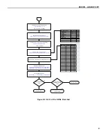
AHRI Selection 

Process

Break-in 

Requested?

Break-

in Per Participant’s 

Instructions (

Participant’s 

Expense)

First Test Sample 

Certification Testing

Rated Values Pass 

Certification Test?

Complete

Yes

No

No

Yes

First Test Failure 

See Appropriate 

Chart for First 

Test Failure 

Options


Figure D1: Selection and Testing Process 


Summary of Contents for OM 210

Page 1: ...NERS AND AIR SOURCE HEAT PUMPS INCLUDES MIXED MATCH COILS RATED BELOW 65 000 BTU H CERTIFICATION PROGRAM 2111 Wilson Blvd Suite 500 Arlington Virginia 22201 703 524 8800 AHRI OM 210 240 JANUARY 2017 Sponsored and administered by ...

Page 2: ...fication Marks hereinafter referred to as the Marks The Marks are the Participant s public representation that the ratings of randomly selected units have been verified by an independent laboratory in accordance with test procedures prescribed by this operations manual A Certification Agreement is executed between the manufacturer and AHRI specifying the conditions under which such Ratings and the...

Page 3: ... Determination of BMGs for Calculating the Number of Tests System Manufacturer 2 1 5 2 ICM BMG Criteria 2 1 5 2 1 Determination of ICM BMG Coil Capacity Range for Calculating the Number of Tests 2 1 6 NAECA Compliance 2 2 Qualification Process 2 1 Original Equipment Manufacturer OEM Applicants 3 STEP 2 1 1 Certification Application Package 3 STEP 2 1 2 Processing Application Package 3 STEP 2 1 2 1...

Page 4: ...ak in Operation of Test Units 7 3 9 Certified Data 7 3 9 1 Unitary Small Air Conditioners Systems and Mixed Match Coils Air Cooled under 65 000 Btu h 19 000 W 7 3 9 2 Unitary Small Air Conditioners Systems and Mixed Match Coils Water Cooled and Evaporatively Cooled under 65 000 Btu h 19 000 W 7 3 9 3 Unitary Small Air Source Heat Pumps Systems and Mixed Match Coils Air Cooled under 65 000 Btu h 19...

Page 5: ...nge Test Pass 14 4 2 2 2 ICM Challenge Test Failure 14 4 3 Test Challenge Fees 14 4 3 1 Final Outcome System Challenge Test Failure 14 4 3 2 Final Outcome ICM Challenge Test Failure 14 4 3 3 Final Outcome ICM Challenge Test Pass 14 5 AHRI Directory of Certified Product Ratings Data Listings 5 1 Publication of Ratings in Certified Directory 15 5 2 Data Forms 15 5 2 1 Making Changes to Submissions 1...

Page 6: ...ubmittal Requirements for Low Stage 23 Table B3 DOE HSV Test Data 25 Table B4 Simulation Inputs for High or Single Stage 25 Table B5 Simulation Inputs for Low Stage 26 Table E1 ICM BMG Definitions 37 Table E2 ICM BMG Bucket Coil Capacity 38 Figures Figure B1 Equation Coefficients 24 Figure B2 Typical Condenser Capacity Curve 27 Figure B3 Typical Condenser Power Curves 27 Figure C1 Use of Provision...

Page 7: ...ndix D Compliance Program Flow Charts 30 Appendix E Independent Coil Manufacturer BMG Definitions 38 Appendix F Setup Commissioning and Operating Checklist for Laboratory Personnel 39 Appendix G Coil Geometry Screening 40 Appendix H Uniform Test Method for Measuring the Energy Consumption of Central Air Conditioners and Heat Pumps Normative 44 APPENDIX I Secondary Capacity Check Requirements 67 ...

Page 8: ......

Page 9: ...ransfer heat between refrigerant and heat sink outside the conditioned space 1 2 5 Single Packaged System Any Unitary Air Conditioner or Air Source Unitary Heat Pump that has the means for air circulation and heat removal air cleaning and the controls thereof in the same cabinet 1 2 6 Split System Any Unitary Air Conditioner or Air Source Unitary Heat Pump that has one or more of the major assembl...

Page 10: ...or coil surface area and the same outdoor air quantity 1 5 1 1 Determination of BMGs for Calculating the Number of Tests System Manufacturer When calculating the number of tests for a Participant s annual testing requirement AHRI shall take the number of active BMGs at the time of selection The number of tests shall be reviewed again at a later date to determine if additional tests are required Th...

Page 11: ...information may be needed to meet EPA ENERGY STAR program requirements STEP 2 1 2 Processing Application Package STEP 2 1 2 1 Performance Certification Agreement for Original Equipment Manufacturer OEM Agreement No further action required beyond that listed in Section 4 STEP 4 2 of the AHRI General Operations Manual STEP 2 1 2 2 Participation and Licensing Fee Invoice Payment of the Participation ...

Page 12: ...isposal If any of these units fail any of the Operating Tests the second sample selected shall pass in order to qualify into the program If the second sample does not pass then that model and BMG shall not be entered into the Directory and the Applicant shall cease production and sale of the failed model and BMG in order to qualify into the certification program A new sample shall be selected and ...

Page 13: ...anual 3 Equipment Selection and Testing 3 1 Annual Testing Requirement 3 1 1 System Manufacturers 20 of a Participant s BMGs shall be tested annually with a minimum of two 2 models for the USAC and or the USHP Certification Programs as applicable Fractional models shall be rounded up to the nearest whole number The number of tests required of the Participant shall be reviewed by AHRI throughout th...

Page 14: ...lections shall be complete systems the Participant s shall choose which systems are provided first The USAC and USHP certification programs are treated separately For example if a Participant receives notification of AHRI selections on January 1st for both USAC and USHP within 45 calendar days the Participant must provide at least 50 of their selections for both programs The Participant may not pr...

Page 15: ...on of Test Units A Participant at its expense shall have the Laboratory operate the equipment for a specified time prior to testing The break in request should be listed in the comments section of the Directory 3 9 Certified Data In accordance with the Standard the following certified ratings are verified by test 3 9 1 Unitary Small Air Conditioners Systems and Mixed Match Coils Air Cooled under 6...

Page 16: ...le is certified with a lower CD not less than zero For heat pumps at the completion of heating mode and frost accumulation tests the Laboratory calculates the HSPF with CD default factor 0 25 3 15 DOE C and D Tests If the calculated SEER is less than 95 of the certified SEER the sample may proceed through the DOE C and D tests at the Participant s option and expense to obtain a tested CD value The...

Page 17: ...le Certified Rating Test Failure When the Participant is notified of a first sample certified rating failure the Participant has seven 7 calendar days to select one 1 of the following options Re rate all models within the failed sample s BMG proportionate to the failed test s results Re test the same sample if the sample has operated less than 16 hours including any break in running time After 16 ...

Page 18: ... option Additional tests shall not count toward the number of tests that a qualified condenser can be used refer to Section 3 18 1 3 Second Sample utilizing same model coil and different System Manufacturer condenser Direct AHRI to select and test a new sample coil with an Outdoor Unit from a different System Manufacturer The coil shall be rated with the Outdoor Unit selected Expenses for obtainin...

Page 19: ...l rating shall remain and no re rates shall be needed d If any descriptor rating falls below 95 of the certified rating the Participant may choose to continue testing in the plan or to concede to a re rate to the second sample s test results In the later case the first additional test statistic shall stand 2 If any descriptor still falls below the 95 threshold a second additional test shall be per...

Page 20: ...h a 90 confidence limit To derive at the statistical rating LCL is divided by 0 95 The lower of either the mean or statistical rating is used to compare against the certified rating If the analysis shows that the product rates above 95 of the Participant s rating the rating shall pass if it does not then the rating fails The statistical analysis calculations are taken from the Code of Federal Regu...

Page 21: ...ple in accordance with the Participant s installation instructions If a range is provided the mean of the range shall be used for the test For ICMs the Laboratory shall follow the ICM s charging instructions If no charging instructions are provided by the ICM the Laboratory shall charge per the System Manufacturer s installation instructions 3 21 Consequences for Improper Ratings 3 21 1 Double Sel...

Page 22: ...ing another Outdoor Unit and testing shall be paid for by the challenged Participant The coil shall be rated with the Outdoor Unit selected 4 3 Test Challenge Fees For challenge tests the same fees apply as those for regularly scheduled testing The cost of all fees e g selection sample shipment and disposition and testing associated with the challenge test shall be borne by one of the three partie...

Page 23: ...mperature Heating Standard Rating Capacity Btu h W if applicable Low Temperature Heating Standard Rating Capacity Btu h W if applicable Region IV Heating Seasonal Performance Factor HSPF if applicable Indoor Full Load Air Volume Rate A2 SCFM Indoor Cooling Intermediate Air Volume Rate Ev SCFM Indoor Cooling Minimum Air Volume Rate B1 SCFM Eligibility for Tax Credit Energy Guide Label Additional da...

Page 24: ...t as being the most likely to be sold For multi split units the HSVTC represents highest sales model family A System Manufacturer Participant shall designate a HSVTC within each BMG Two 2 or more HSVTCs are permitted within the same BMG The HSVTC within each BMG shall be indicated and affirmed by the Participant s senior engineering executive and senior marketing executive 5 5 1 Single Speed Split...

Page 25: ... system s rating 5 9 1 Test Locked Ratings Section 5 9 also applies to ratings that are locked for testing For ratings that are locked the ICM can only adjust the ratings no more than the same percentage of de rate in the system manufacturer s rating 5 10 Specific Indoor Coil Data Participants can download additional specific indoor coil data and condenser curve coefficients from the Directory 5 1...

Page 26: ...ut justifying the rating Based on AHRI s approval the listings shall be published in the Directory 5 12 1 2 Entering Air Handler Ratings If a Participant adds ICM combination air handler i e a blower unit and evaporator coil combined ratings when the System Manufacturer HSVTC combination is coil only Participants shall be required to provide test reports and or ARM simulation input output justifyi...

Page 27: ... a Participant is adding or editing model listings the Directory shall validate whether the new rating exceeds the range specified on the condenser characteristics table For ratings submitted that exceed the regional efficiency range the Directory shall prevent the ratings from being added Participants shall edit the range for SEER and or HSPF in the condenser characteristics table and then resubm...

Page 28: ...he mixed Indoor Unit assembly shall not be greater than 120 of the IRV of the matched certified Indoor Unit assembly of the System Manufacturer IRV shall be rounded to the nearest 1 C Calculation of IRV 𝑁𝑢𝑚𝑏𝑒𝑟 𝑜𝑓 𝑇𝑢𝑏𝑒𝑠 𝑖𝑛 𝑎 𝑅𝑜𝑤 𝑆𝑙𝑎𝑏 𝐹𝑖𝑛𝑛𝑒𝑑 𝐻𝑒𝑖𝑔ℎ𝑡 𝑉𝑎𝑙𝑢𝑒 𝑜𝑓 𝐹𝑖𝑟𝑠𝑡 𝐷𝑖𝑚𝑒𝑛𝑠𝑖𝑜𝑛 𝐼𝑑𝑒𝑛𝑡𝑖𝑓𝑖𝑒𝑑 𝑖𝑛 𝐸𝑣𝑎𝑝𝑜𝑟𝑎𝑡𝑜𝑟 𝑇𝑢𝑏𝑒 𝐶𝑒𝑛𝑡𝑒𝑟𝑠 Ex If Evaporator Tube Centers 1 00 x 0 625 the value of the first dimension identified in ...

Page 29: ... restrictor then the flow factor for the mixed system is based on the fixed indoor restrictor with cooling capacity closest to the tested system The mixed flow factor shall be within the range of 100 125 C If the certified matched system combinations have only TXV indoor then the mixed system shall be TXV 4 The mixed Indoor Unit assembly shall meet the same burst strength requirements as the match...

Page 30: ...terized by the general linear equation Gross Capacity or Power m Evaporator Saturation Temperature b Where m slope b intercept Condenser power power watts associated with the Outdoor Unit only no indoor power is to be included Condenser capacity total capacity Btu h with no indoor power Evaporator Saturation Temperature the refrigerant saturation temperature based on the outlet refrigerant pressur...

Page 31: ...mperatures 2 Simulations shall take into account the pressure drops associated with the liquid and suction interconnecting lines 3 Simulated evaporator superheat is to remain a constant value in the case of HSVTC systems utilizing an expansion valve For fixed orifice capillary tubes or other fixed flow control devices the superheat shall remain at a constant value for all A test simulations and re...

Page 32: ...orm least squares linear regression using simulations Ref Table 2 Calculate slopes m1 m2 m3 m4 from simulations Table 2 Calculate intercepts b1 b2 b3 b4 based on HSVTC data in Table 1 Determine the values required in Table 2 Calculate slopes and intercepts from regression m1 m2 m3 m4 b1 b2 b3 b4 Correct intercepts based on HSVTC data in Table 1 Determination of Coefficients Complete No Yes ...

Page 33: ...Mean of the values measured during HSVTC testing Mean Evaporator Temperature B test F Input or Calculated value Calculation based on saturation temperature for pressure above Item Value A Test Evaporator Temperature T1 F Saturated suction temperature evaporator leaving Condenser Capacity A test T1 btuh Includes pressure loss of interconnecting lines with addition of indoor power converted to btuh ...

Page 34: ...onverted to btuh Condenser Power B test T2 watts Compressor OD air mover power only F Test Evaporator Temperature T1 F Saturated suction temperature evaporator leaving Condenser Capacity F test T1 btuh Includes pressure loss of interconnecting lines with addition of indoor power converted to btuh Condenser Power F test T1 watts Compressor OD air mover power only Evaporator Temperature T2 F Saturat...

Page 35: ...0000 22000 24000 26000 28000 30000 32000 34000 36000 38000 40 41 42 43 44 45 46 47 48 49 50 51 52 Evaporator Temperature F Condenser Capacity btuh A Test B Test HSVTC HSVTC Typical Condenser Power Curves 2000 2100 2200 2300 2400 2500 2600 2700 40 41 42 43 44 45 46 47 48 49 50 51 52 Evaporator Temperature F Condenser Power watts A Test B Test HSVTC ...

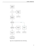
Page 36: ...USE OM JANUARY 2017 28 APPENDIX C CONDENSING UNITS FOR COIL ONLY CERTIFICATION Figure C1 Use of Provisionally Qualified Outdoor Units for ICM Testing ...

Page 37: ...USE OM JANUARY 2017 29 Figure C2 Use of Unqualified Outdoor Units for ICM Testing ...

Page 38: ...reak in Requested Break in Per Participant s Instructions Participant s Expense First Test Sample Certification Testing Rated Values Pass Certification Test Complete Yes No No Yes First Test Failure See Appropriate Chart for First Test Failure Options Figure D1 Selection and Testing Process ...

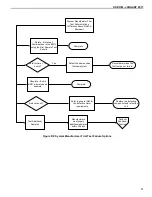
Page 39: ...me unit as first sample test Retest determines the first test pas or failure Obsolete Entire BMG is derated and obsolete Complete Test Additional Samples Manufacturers must supply additional samples within 30 days Conduct Additional Testing Yes Defective unit Refer to general OM for the defective claim requirements Replace the defective component and retest the unit Figure D2 System Manufacturer F...

Page 40: ...Complete Test Second Sample with a Different Outdoor Unit Same coil AHRI selects outdoor unit from another manufacturer Second Sample Test Rerate all combinations in that BMG Rerate will be the same by which the tested unit failed Obsolete All combinations in that BMG will be derated and obsolete Test Additional Samples Manufacturers must supply additional samples within 30 days Conduct Additional...

Page 41: ...rtification Testing Certified Values Pass Certification Test Complete Second Test Failure Rerate the Second Sample Combination and All Models within the BMG Rerate Original Failed Tested Combination Figure D4 ICM Second Sample Test ICM Second Sample Test with Different Outdoor ...

Page 42: ...ith Samples Do the Results Meet the Testing Requirement Yes Yes No No Testing is Complete Yes Is this Last Additional Sample Testing is Complete Rerate all combinations in that BMG Rerate will be the same as the failure No Yes Does Participant Continue Testing Rerate all combinations in that BMG Rerate will be the same as the failure Testing is Complete No Yes Repeat the Additional Sample Test Pro...

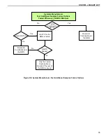
Page 43: ...nations in the BMG HSVTC for the BMG is tested HSVTC Passes Only the Tested Combination is Rerated The rest of the BMG is saved No Yes Yes No Yes No Figure D6 System Manufacturer Test Additional Samples Failure Options Systems Manufacturer Test Additional Samples Failure Options Tested Efficiency NAECA Minimum ...

Page 44: ...bsoleted and Rerated Values are Shown No Single Combination can be Tested to Restore Ratings for that Combination Is HSVTC Test Requested No HSVTC is Tested for BMG Yes HSVTC Test Pass All Combinations within the BMG are Rerated by the by which the Tested System Failed Except the HSVTC Combination Rerated Combination Applicable Minimum Complete Yes Rerated Combination is Obsoleted and Rerated Valu...

Page 45: ...licable to Non Air Cooled Product Evaporator Fin Type Flat Corrugated Hi Performance Lanced Louvered N A This option only applicable to Non Air Cooled product mixed case Evaporator Fins Inch Whole Number Two 2 fins inch per BMG example 8 9 10 11 12 13 14 15 etc Evaporator Tube OD 1 4 in 5 16 in 3 8 in 7 8 in 1 2 in 1 x 0 072 in rifled 1 4 in rifled 5 16 in rifled 3 8 in rifled 1 2 in rifled 7mm N ...

Page 46: ...finitions I Fin Definitions a Flat A flat surface without amplitudes b Corrugated A flat surface modified with angular amplitudes c Hi performance A flat surface modified with sine wave amplitudes but no lances or louvers d Lanced Louvered A surface modified with raised lances or louvers II Slab An independent tube coil assembly or module used for heat transfer between refrigerant and air For exam...

Page 47: ...ion instructions 3 Verify the ductwork meets ASHRAE 37 requirements 4 Inspect indoor ductwork for leaks 5 Verify that the indoor coil is sitting in the housing and is positioned correctly 6 Inspect the trap for condensate is clear of obstructions and check if the condensate is leaving 7 Verify that the correct nozzles are selected for the given airflow range 8 Verify that the voltage to be applied...

Page 48: ...of the flowchart the ratings are subject to the coil geometry screening program The program shall generate a rating based on submitted data from the ICM This rating is then compared with the System Manufacturer s inputted data The ratings of the mixed coil shall not exceed 6 of the output rating generated by the coil geometry screening program C Participants have the option to perform an AHRI test...

Page 49: ...ta Data consists of IndoorCoilAirQty EvapGrossFinnedFaceArea EvapTubeOD SlabFinnedLength NumberofTubes EvapFinsPerInch 1 Start with outdoor and indoor model numbers Calculate systems tube surface EvapTubeOD PI SlabFinnedLength NumberofTubes System Design Stages Single Stage N Y Get Systems Coil only ratings Done Figure G1 Part 1 of the ORNL Flowchart ...

Page 50: ...USE OM JANUARY 2017 42 Figure G2 Part 2 of the ORNL Flowchart ...

Page 51: ... Difference ICM Flow Control Value Systems Flow Control Value Calculate SEER difference System SEER 1 Total SEER effect ICM Rated SEER Rating Validated by AHRI ARM Software 94 Y N Rating allowed ITS Lab test data 95 before rating is allowed Flow Control Type Accessory Value Non Bleed TXV TDR or LLS 0 45 Bleed TXV TDR or LLS 0 35 Non Bleed TXV 0 30 Bleed TXV 0 20 Capillary Tube TDR or LLS 0 15 Orif...

Page 52: ...F CENTRAL AIR CONDITIONERS AND HEAT PUMPS NORMATIVE Foreword This appendix to the AHRI USE OM is the LEAP Process referred to in Section 3 2 2 Appendix to OM 210 240 Certification of Laboratory Facilities Used To Determine Performance of Unitary Air Conditioning Air Source Heat Pump Equipment ...

Page 53: ...boratory Facility 62 3 8 2 OEM Laboratory Facility 62 3 9 Laboratory Evaluation Adjustment Plan LEAP 62 3 10 Psychrometric Test Facility 62 3 10 1 Indoor Room 62 3 10 2 Outdoor Room 62 3 11 Seasonal Energy Efficiency Ratio SEER 63 3 12 Shall or Should 63 3 12 1 Shall 63 3 12 2 Should 63 3 13 Standard Air 63 3 14 Test 63 3 14 1 Pre conditioning Test 63 3 15 Test Condition Tolerance 63 3 16 Test Ope...

Page 54: ...Procedure 76 5 3 5 Data to Collect 76 5 3 6 Interpretation and Application of the Data 76 5 3 7 Reporting and Retention of the Data 77 5 4 Full System Psychrometric Round Robin Testing 77 5 4 1 Purpose of the Test 77 5 4 2 Selection of Equipment 77 5 4 2 1 Equipment Classification 77 5 4 2 2 Equipment Size and Configuration 77 5 4 3 Test Setup 77 5 4 3 1 Test System Preparation Charge 76 5 4 3 2 T...

Page 55: ...USE OM JANUARY 2017 47 Figure K1 Nozzle Combination Tests 66 Figure K2 Passive Pressure Drop Device 75 ...

Page 56: ...execution Tolerance changes may be made by the Committee by providing a request to the AHRI USE Compliance Committee and shall be performed with the authority of the Committee only Section 1 Purpose 1 1 Purpose The purpose of the appendix is to establish for laboratory facilities used to determine performance of Unitary Air Conditioners and Air Source Unitary Heat Pumps definitions test requiremen...

Page 57: ... during auditing of performance ratings 3 8 Laboratory Facility Any organization that has psychrometric test rooms data acquisition and other equipment necessary to determine the performance of an Unitary Air Conditioner or Unitary Heat Pump with the intent of using the facility for Laboratory Certification Tests or qualifying new product under the penalty mode in the latest edition of AHRI USE Op...

Page 58: ... between the maximum temperature and the minimum temperature measured during a Test 3 17 Third Party Laboratory An independent non AHRI member laboratory facility that operates under contract with AHRI to perform Laboratory Certification Tests on Unitary Air Conditioners and Unitary Heat Pumps under the scope of the AHRI Unitary Small Equipment Section Operations Manual 3 18 Unitary Air Conditione...

Page 59: ...ue to relatively high power requirements Individual banks shall have the capability of being switched independently 5 1 3 Test Setup 5 1 3 1 The UUT shall be set up in the Indoor Room in accordance with ASHRAE Standard 37 Section 6 4 through Section 6 6 5 1 3 2 All indoor electrical energy shall be measured with instrumentation which is in accordance with Section 5 4 of ASHRAE Standard 37 5 1 3 3 ...

Page 60: ...SCFM measured 5 1 4 2 3 For each potential nozzle combination at least three 3 air flow rates shall be tested as described in Table K1 For the purpose of this Section 5 1 test shall be construed to be a single air flow rate for a given nozzle combination 5 1 4 3 Test data for each air flow rate shall be recorded at equal intervals with a maximum interval period of one 1 minute over a 30 minute per...

Page 61: ... Static Press At Supply Inlet Measured SCFM Fan WATTS Heater Watts Total Watts Electrical Heat BTUH Input Delta T Measured Sensible Capacity Sensible Capacity Heat Balance Barometer 0 8 12 1 8 12 2 8 12 0 8 12 1 8 12 2 8 12 0 8 12 1 8 12 2 8 12 Typical values required to evaluate full range of operation Nozzle Delta P is limited between 0 6 and 3 0 inches of water column at Nozzle Plate ...

Page 62: ...rential temperature R 5 1 5 2 The following data is the minimum to be collected for each nozzle chamber for validation of conformance with ASHRAE 37 Section 6 2 Section 6 3 and Figure 5 D1x y distance from center of 1st nozzle to inside edge of nozzle chamber in both horizontal x and vertical y directions in D2x y distance from center of 2nd nozzle to inside edge of nozzle chamber in both horizont...

Page 63: ...d with a given nozzle combination is within 2 0 then no nozzle combination air flow rate correction is required Cnz 1 K4 Where Cnz nozzle correction factor 5 1 6 2 2 If the energy balance BSH for each air flow rate tested with a given nozzle combination falls between either 2 1 and 4 0 or 2 1 and 4 0 then a nozzle combination air flow rate correction factor shall be assigned to that particular noz...

Page 64: ...e Capacity Ratio shall be calculated L S and reported as a percentage If this ratio exceeds 5 an investigation into the humidity measurement error should take place 5 1 6 2 2 5 No correction either single or equations will be allowed that exceeds a 4 correction Nozzle combinations that have a BSH greater than 4 0 shall not be used during Laboratory Certification Tests 5 1 6 2 3 Corrective actions ...

Page 65: ... may be varied separately from electrical energy supplied to the rest of the UUT Typically the psychrometric Outdoor Room power supply and measurement equipment will need to be used due to relatively high power requirements Individual banks shall have the capability of being switched on and off independently 5 2 3 Test Setup 5 2 3 1 The UUT shall be set up in the Indoor Room in accordance with ASH...

Page 66: ...ly recommended that the active variac voltage control be disabled during the cyclic part of this test 5 2 4 5 The thermocouple or thermocouples attached to the largest thermal mass in the test facility out of line of sight of the heater shall be recorded on a minimum of ten second intervals for the duration of the six minute on time Note that if more than one 1 large thermal mass is expected then ...

Page 67: ... ASHRAE Standard 116 sections 7 4 3 4 5 and 9 2 2 for each of the last 6 to 8 cycles mcpm qts tm 0 tm ΘI K12 5 2 6 5 Report mcpm as the mean of mcpm for last 6 to 8 cycles Cycle equilibrium is defined in ASHRAE 116 8 2 4 2 as three 3 consecutive cycles in which the integrated T for the on portion of the cycle does not vary by more than 0 3 F and the total watts for the complete on off cycle does n...

Page 68: ...ification A passive pressure drop device is a box with nominal outside dimensions approximating a cased coil see Table K2 and Figure K2 below shall be constructed with fixed restrictor plates to simulate the pressure drop associated with an indoor coil at nominal airflows An outlet duct shall be sized according to ASHRAE Standard 37 Section 6 4 4 and shall be used to measure the outlet pressure 5 ...

Page 69: ... device shall be set up with an entering and leaving duct with the dimensions outlined in Figure 8 of ASHRAE Standard 37 The entering duct shall have free flow of air and shall not be on top of a bottom damper system employed for cyclic testing 5 3 3 2 2 Conventional Psychrometric Testing Configuration This testing will utilize the bottom damper system and whatever means pressure skirt with four m...

Page 70: ...wing data is the minimum to be collected for this testing BST static pressure drop balance Pa pressure barometric in Hg Pn pressure at nozzle throat in H2O Pv velocity pressure at nozzle throat or static pressure difference across the nozzle in H2O QS measured air flow rate SCFM ta1 temperature air entering indoor side dry bulb F t a1 temperature air entering indoor side wet bulb F tn nozzle tempe...

Page 71: ...certified values with at least 95 of the certified rating and if a split system be within 10 on all condenser curves The system type shall be a simple base model without proprietary controls or other features that would complicate the testing The nominal capacity of the initial system would preferably be 3 tons The size of the round robin system shall be rotated on a yearly basis to ensure the ent...

Page 72: ...apacity balance shall be within the tolerances specified in Section 5 5 6 of this appendix 3 System state points shall be within a 5 psig for any high side pressure b 2 psig for any low side pressure c 1 F superheat at charging location for piston expansion systems d 1 F subcooling at charging location for expansion valve systems Any questions on the testing process shall be referred to the Commit...

Page 73: ...r at least five 5 consecutive A tests during the cooling Tests of the Full System Psychrometric Round Robin Testing see Section 5 4 5 5 4 4 The condensate mass flow rate draining off of the indoor coil shall be measured during each of the five 5 consecutive A or A2 Tests 5 5 4 4 1 At a minimum measure the weight or volume at the beginning and at the end of each individual A or A2 Test Calculate th...

Page 74: ... it could possibly indicate a psychrometer inaccuracy issue either control or measurement or a mixing issue that would require improvements to the facility If changes are made to any test apparatus set up or calibration this battery of tests must be re run in their entirety 5 5 6 3 In addition the latent capacity qlcc based on condensate flow for each of the last three 3 consecutive A or A2 Tests ...

Page 75: ... Cooled Section 3 Definitions 3 1 Code Tester A nozzle airflow measuring apparatus as defined by ASHRAE Standard 37 Section 6 2 3 2 Flow Meter Assembly A mass flow meter associated tubing associated valve assemblies sight glasses and any other associated components that add internal volume to the operating system 3 3 Pressure Transducer Assembly A pressure transducer associated tubing associated v...

Page 76: ... 2 The absolute value of HB shall be 6 0 or less on all tests except for H3 which may be greater than 6 0 if all other tests are less than 6 0 5 3 For any products that meet the scope defined in Section 2 where the requirements of Section 6 or Section 7 cannot be met the Unitary Small Equipment Engineering Committee shall be contacted for resolution Section 6 Refrigerant Mass Flow Method Requireme...

Page 77: ...he tube The wires are secured to the tube via soldering or welding without burning insulation or melting wire and The wires outside of the joint described in Section 6 2 3 3 3 are prevented from touching each other or other metallic surfaces preferably by applying electrical tape between the wire and the tube outside of the solder bed 6 2 3 4 Each and every TC shall be applied per ASHRAE Standard ...

Page 78: ... at the Outdoor Unit then the outdoor air enthalpy method shall be used per Section 7 of this appendix 6 4 4 If needed in order to improve HB the following adjustments are permitted If such adjustments are made the test report shall indicate the adjustments 6 4 4 1 Pressures used may be adjusted for elevation differences between the actual pressure tap location and the pressure transducer If the p...

Page 79: ...ns 7 2 4 4 Each and every TC shall be applied to the tubes per ASHRAE Standard 41 1 Section 10 7 2 4 4 1 There shall be no more than 3 turns of wires contacting each other 7 2 4 4 2 The wires shall be tinned or soldered together before application to the tube 7 2 4 4 3 The wires shall be secured to the tube via soldering or welding without burning insulation or melting wire 7 2 4 4 4 The wires out...

Page 80: ...ts that have air outlets next to the ground In these cases the 6 minimum is not required 7 5 1 3 Exception 3 Units with flanges the duct shall be the same size as the duct flanges 7 5 2 For units that discharge air partially horizontally the outside dimensions of the duct shall be at least 2 feet greater than the air opening of the unit 7 5 3 Rectangular ducts may be used on units with round openi...

Page 81: ...et capacities shall be adjusted accordingly 7 6 4 Immediately following the FA test conducted per Section 7 6 2 of this appendix the ductwork meeting requirements of Section 7 5 shall be added to the Outdoor Unit and a Closed Duct test shall be conducted All steady state requirements per AHRI Standard 210 240 ASHRAE Standard 37 and 10 CFR 430 Appendix M to Subpart B shall be met During this CD tes...

Page 82: ...within 2 0 of the FA test 7 6 4 13 Absolute value of HB shall be within 6 0 7 6 4 14 Outdoor duct static pressure during this closed duct test shall be recorded with all other parameters including average minimum and maximum 7 6 5 All other tests in each operational mode may be made with the outdoor duct remaining connected to the Outdoor Unit as long as the same average outdoor duct static pressu...

Reviews: