background image

INSTRUCTIONS FOR USE 

AGP 300 – 600 PRO 

Rev.02/2019


32 

7.9.3


Fan 


Figure 7.8 

The Ø812 fan (33'') is  driven by the 
multiplier gearbox.  
It contains a centrifugal clutch which 
ensures a soft starting of the fan.  


7.9.4


Distribution cube and adjustable nozzle holders 


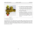
Figure 7.9 


The blower has two distribution cubes designed to distribute the flow to individual nozzles. 
The air flow can be individually directed through the regulator and two valves to the first or 
the other section (18/2). If the regulator has four valves, the flow can also be directed to four 
sections (18/4). 


The nozzle holders are connected to the distribution cube with a flexible hose. It is possible 
to adjust the height and direction of nozzle holders. 

Summary of Contents for AGP 300 PRO

Page 1: ...IST BLOWERS AGP 300 PRO AGP 400 PRO AGP 500 PRO AGP 600 PRO INSTRUCTIONS FOR USE AGROMEHANIKA reserves the right to design modifications or product changes without any liabilities to inform the customer before and after each change ...

Page 2: ... for chemical protection of plants Reliability and performance of the device depends on your care for the device Before connecting the spraying device to a tractor carefully read the instructions for use and heed to them while operating the machine Instructions contain essential information on effective and safe use and long life of the machine ...

Page 3: ...ction 13 2 13 Maintaining protection equipment 14 2 14 Safe operation 14 2 15 Safe maintenance 15 2 16 Road transport 15 2 17 Procedures in accidents with chemicals 16 2 18 Regulations regarding machine use 16 3 DRIVE CARDAN SHAFT NOT INCLUDED 17 3 1 Operator s safety 17 3 2 Connection of cardan shaft 17 4 SAFETY SIGNS ON MACHINE AND INSTRUCTIONS FOR USE19 5 DESCRIPTION 21 5 1 Machine transportati...

Page 4: ...TIONAL EQUIPMENT 39 9 1 External cleaning kit 39 9 2 Packaging and strainer cleaner under the lid 39 9 3 Suction basket 40 9 4 Nozzle holder for spraying tall crops 41 10 PRESSURE REGULATOR 42 10 1 The PR8 pressure regulator 42 10 1 1 Manual pressure regulator PR8F 2EC 42 10 1 2 Remote pressure regulator PR8ECF 2EC 42 10 2 The PR9 pressure regulator 43 10 3 Regulator markings 44 10 3 1 Standard mo...

Page 5: ...3 5 Pump 56 13 6 Multiplier gearbox 56 13 7 Drive cardan shaft 56 13 7 1 Bolts 57 1270 57 13 9 HOSE JUNCTIONS 57 13 10 OTHER PARTS 58 14 POSSIBLE ERRORS 60 15 TECHNICAL DATA 61 15 1 CHARACTERIZATION 62 15 2 SPRAYER DISPOSAL 62 15 3 MATERIALS AND RECYCLING 62 16 COMBINATIONAL MATRIX 63 17 GENERAL INSTRUCTIONS FOR SPRAYING 64 17 1 Connection for checking the pump flow rate measurement 64 17 2 Nozzle...

Page 6: ...INSTRUCTIONS FOR USE AGP 300 600 PRO Rev 02 2019 18 2 Different calculations 67 18 3 Recommendations 68 19 NOTES 69 ...

Page 7: ...s and method for inspections of such equipment Official Gazette of the Republic of Slovenia No 101 2013 The following harmonized European standards on safety were applied SIST EN ISO 4254 1 2013 Agricultural machinery Safety Part 1 General requirements SIST EN ISO 4254 6 2010 Agricultural machinery Safety Part 6 Sprayers and devices for distributing liquid fertilizers ISO 4254 6 2009 SIST EN ISO 4...

Page 8: ...e the spraying equipment for pumping or spraying this spraying equipment was designed and built for the application of water soluble chemicals on crops which are normally used for the chemical protection of agricultural crops Spraying device is not to be used for pumping or spraying of water based solutions with greater specific weight and viscosity than water chemical solutions whose compatibilit...

Page 9: ...anging component parts make sure that the machine includes all required safety signs Safety signs are available from authorized dealers Learn the operation of your machine and proper handling and control units Ensure that your machine is in good technical condition Each unauthorized change to the machine can diminish its function as well as safe operation and can shorten its life span 2 3 Readines...

Page 10: ...at you do not have direct contact with chemical products Handle chemical products as you would poisons Choose chemical products which are least dangerous to your health most effective and easy soluble Always read instructions for use given on the chemical products Regard regulations safety measures and use instructions When working use respiratory protection such as gas mask helmet with fresh air ...

Page 11: ... ingesting food and liquids Disable children and animals to access the machine until it is properly cleaned After use clean the machine properly and store it in a suitable place so that unauthorized persons do not have access After working with chemical products take a thorough bath Clean and wash the machine after each use and before each maintenance procedure If you have any health issues while ...

Page 12: ...ffic regulations do not enter the tank while preparing or cleaning never set working pressure above 15 bar maximum allowed working pressure do not start working until you are sure that there are no unauthorized people in the vicinity of the machine pull out the key from the key lock after you have finished working to prevent sudden unwanted start of the machine 2 8 Dangers caused by liquids under ...

Page 13: ...e tractor closed It is recommended that the operator has a hermetically closed cabin which allows the operator to create overpressure with aeration of fresh air that disables chemically polluted air to enter the cabin While spraying it is recommended that the operator stays in the cabin for about 90 95 of the time so the chemical products cannot have influence on his or her health Should the opera...

Page 14: ...rganic chemicals o Before using the mask check the tightness and sealing of it Check the mask for damages and make sure that the outer valve is clean and can be closed without any problems Write down the date of the last usage of the filter The A2P2 filter must be replaced once a month nevertheless how many times it was used Filter B must be replaced after every single use The filter must be used ...

Page 15: ...t is not allowed to sprinkle in foggy and rainy weather or when the wind speed exceeds 4 m s The direction of spraying must be adjusted to the wind direction If there are two tractors with spraying appliances working simultaneously they must not pollute each other s working area atmosphere Never bring personal things in the area of spraying or when handling chemicals Before every meal thoroughly c...

Page 16: ...maged parts Remove excess oil grease or any other debris Disconnect the battery before you start to adjust the electrical system or perform welding on the machine During maintenance of the machine or cleaning the nozzles use appropriate protection equipment in accordance with the regulations It is strictly forbidden to release chemicals into the environment 2 16 Road transport Do not drive the mac...

Page 17: ...ning symptoms sweating dizziness depression headache sickness immediately stop working take off wet clothes remain calm if you feel sick because of consumption of chemicals try to throw up lay on your side immediately call for medical help and let the physician see the label of the chemical so he or she will be able to determine the type of poisoning easier In case of suspected poisoning the patie...

Page 18: ...ardan shafts without protection Do not touch rotating cardan shafts The safety distance to a rotating cardan should not be less than 1 5 m Secure protection elements with chain from turning Make sure that the protection of the cardan on the tractor and connection is well connected attached 3 2 Connection of cardan shaft The first mounting of the cardan shaft should be performed as follows Mount th...

Page 19: ...dan shaft avoid angles larger than 15 When using safety cardan shafts fit an Allen screw with torque of 40 Nm Check the torque after two 2 minutes of operation WARNING Always mount the female end of the cardan shaft to the tractor Connect the chains in order to prevent rotation of safety covers WARNING Covering of cardan pipes must be at least 150 mm ...

Page 20: ... of the machine Warning maximal allowed pressure in the spraying device 12 bar Warning keep away from rotating drive shafts Warning direction of cardan shaft rotation Warning read the instruction manual before connecting the device to the tractor for the first time It is prohibited to clean grease or maintain the device as long as it is running Prohibitions It is not prohibited to smoke while work...

Page 21: ... number of revolutions of tractor s drive shaft PTO 2 Sprayer identification plate 7 Sign for the reservoir containing clean water for hand washing 3 Litre scale 8 Signal lights 4 General safety signs 9 Speed adjustment and multiplier gearbox deactivation sign 5 Signs for correct manipulation 10 Control signs ...

Page 22: ...r side of the mist blower directs the air to the left to the right and to the whole height of the habitat Due to the prolonged distance of drops through the habitat the airflow is directed diagonally to the row Hence the drift of the protective agent towards the tractor is reduced to a minimum The fan enables the user to adjust the speed and amount of air to the type of plantation and to the lushn...

Page 23: ...INSTRUCTIONS FOR USE AGP 300 600 PRO Rev 02 2019 22 Figure 5 2 ...

Page 24: ...INSTRUCTIONS FOR USE AGP 300 600 PRO Rev 02 2019 23 5 2 Sprayer component parts Figure 5 3 ...

Page 25: ...15 Hand washing tap 16 Nozzle consumption table 17 Safety and warning labels 18 Additional reservoir valve drain 19 Selector valve main or additional reservoir 20 Mist blower frame 2 Main reservoir 3 Lid of the main reservoir 4 Lid of the additional reservoir 5 Rinsing reservoir 6 Hand washing reservoir 7 Pump 8 Pressure regulator 9 Suction filter with control valves 10 Case with a fan ...

Page 26: ...total weight allowed max working pressure required power of drive production year and serial number and CE conformity marking 5 3 1 Pump identification plate It is located on the pump and contains all the main information about the characteristics of the pump name and address of the pump manufacturer pump type nominal flow max flow at maximum allowed rotation frequency and maximum allowed working ...

Page 27: ... can connect them with a universal joint Figure 6 1 Figure 6 2 To move the barycentre and the height it is possible to move the lower bolt towards the inner side of the mist blower or downwards WARNING When the mist blower is attached for the first time pay attention to the following Check the correct tire pressure in the tractor see the tractor s operating instructions and the mist blower tires a...

Page 28: ...with a strainer mounted at the top of the main reservoir Do not remove the strainer when the main reservoir is filled with a spraying agent or water The front side of the main reservoir contains an engraved litre scale with a transparent hose attached next to it containing a floating red ball for easier reading of the quantity of chemical agent in the reservoir 7 2 Reservoir lid The reservoir is e...

Page 29: ...er handling insecticides Fill the reservoir with drinkable water Its capacity is 15 litres see technical data 7 5 Mixing nozzle Figure 7 2 To ensure better mixing the machine is fitted with one or two mixing nozzles integrated into the bottom part of the reservoir The mixing nozzle is controlled by means of the diverter valve mounted on the pressure regulator The mixing nozzle is active when the d...

Page 30: ...ter insert 4 Clean the filter insert and mount all parts back together in the reverse order When mounting the parts back together make sure that the metal pin of the locking valve which is located at the extracted part with a yellow lever will be properly inserted otherwise the filter will not function properly Figure 7 3 7 7 Nozzle for cleaning interior of main reservoir Figure 7 4 Nozzle is moun...

Page 31: ...e penetrated with the pointy top of the rinsing nozzle 2 When the entire content of the packaging bottle is emptied push the neck of the bottle or plastic container over the nozzle and to the limiter 3 This activates the nozzle which thoroughly washes the inside of the packaging When the packaging is removed the flow is closed Figure 7 5 7 9 Blower There are two blowers available that differ in th...

Page 32: ...droplets of spray Efficient spraying depends on the quality or air current the amount and speed of air without turbulence Air current is therefore used to ensure quality transport of droplets from the nozzle to the desired parts of plants 7 9 2 Blower components Figure 7 7 1 Safety arc 2 Distribution cube 3 Oil filler plug on the multiplier gearbox and bleed valve 4 Fan 5 Multiplier gearbox 6 Insp...

Page 33: ... Figure 7 9 The blower has two distribution cubes designed to distribute the flow to individual nozzles The air flow can be individually directed through the regulator and two valves to the first or the other section 18 2 If the regulator has four valves the flow can also be directed to four sections 18 4 The nozzle holders are connected to the distribution cube with a flexible hose It is possible...

Page 34: ...lier gearbox with a shaft that propels the fan has a switch off lever mounted at the side that switches off the rotation or speed level of the fan This way the mist blower can be used for other purposes preparing the spraying mixture mixing spraying with a manual spraying lance etc Technical data Multiplier gearbox type COMER D21F Gear ratio i 1 3 5 0 1 5 Lubrication oil SAE 90 Oil volume l 1 75 7...

Page 35: ...w pressure values closes at 0 8 bar and opens at 1 5 bar to prevent the fluid from dripping or leaking out if the flow of the supply or the main valve is closed 7 10 Blower maintenance General maintenance work regular cleaning of nozzle holders regular checking of the anti drip diaphragm and nozzle closing functions checking for and repairing damaged protective screens on the fan Removing all fore...

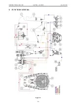
Page 36: ...INSTRUCTIONS FOR USE AGP 300 600 PRO Rev 02 2019 35 8 FUNCTION SCHEMA Figure 8 1 ...

Page 37: ... Pump safety valve 20 External filling 21 Strainer and packaging cleaner 22 Reservoir rinsing nozzle 23 Selector valve for strainer rinsing and reservoir washing free outlet 24 Valve on the pump for selector valve supply 1 Main reservoir 2 Additional reservoir 3 Pump 4 Blower with a fan 5 Multiplier gearbox 6 Nozzles 7 Distribution cube 8 Two mixing nozzles 9 Regulator return flow selector valve 1...

Page 38: ... pump from the main reservoir 17 Figure 8 1 Direct the spray into the pressure regulator 14 Figure 8 1 through the filter 18 Figure 8 1 and pump 3 Figure 8 1 Figure 8 2 Open the selector valve on the regulator 10 Figure 8 1 to mix the spray by means of the mixing nozzle 8 Figure 8 1 and open the supply valve for nozzle sections 11 Figure 8 1 Adjust the selector valve 9 Figure 8 1 so that the exces...

Page 39: ...raying sections 11 Figure 8 1 to ensure a complete emptying of the main reservoir through the nozzles on the spraying pipes 8 1 3 Partial cleaning Partial cleaning of the mist blower includes the cleaning of the suction filter 18 Figure 8 1 the pump 3 Figure 8 1 the pressure regulator 14 Figure 8 1 the distribution cube 7 Figure 8 1 and the nozzles 6 Figure 8 1 without changing the concentration o...

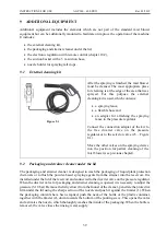
Page 40: ...tor or to the selector valve 23 Figure 8 1 Move the other valves on the spraying device into the position for partial cleaning of the mist blower see previous chapter 9 2 Packaging and strainer cleaner under the lid The packaging and strainer cleaner is designed to wash the packaging of liquid plant protection chemicals or to flush the powder based spraying agents from the strainer into the reserv...

Page 41: ...ed on the filter Stretch the suction hose and submerge the suction basket in the water Please note that the suction height the height difference between the water surface and the pump significantly affects the load on the membranes of the pump The height difference between the pump and the surface of the water should not exceed 3 m Before activating the pump turn the three way valve 17 Figure 8 1 ...

Page 42: ...e these nozzles are made for different spraying requirements range related the angle of spraying is narrower to reach greater distances which also reduces the quality of spraying Another disadvantage is also that the adjustment changes the nozzle flow which means that it is theoretically impossible to control the consumption of spray This can only be achieved by conducting practical tests The inst...

Page 43: ...lve 4 Pressure filter 5 Pressure gauge 6 Pressure connection 7 Return line connection 9 Control panel It is distinguished by a sturdy robust construction from materials of the highest quality to ensure smooth operation at high operating pressures opening and closing of diverter valves by means of solenoid valves easy operation trough the control panel located at the operator s position inside the ...

Page 44: ...the benchmark of quality when it comes to operating the complete range of spraying functions It is used with the system of complete electronic adjustment or operation of the mist blower s spraying functions and is one of the best methods of computer control and operation of the most important working functions for spraying The regulator is operated through AG TRONIK M1 which is specifically design...

Page 45: ...r consists of the regulator type the pressure filter and the number and type of diverter valves installed Example The PR8ECF 2EC marking indicates the pressure regulator PR8 with remote pressure adjustment high pressure filter F marking and two solenoid diverter valves number code EC 10 4 Main components of the pressure regulator 10 4 1 Control panel Figure 10 4 Starting from the basic version the...

Page 46: ...ion 10 4 3 The PR8 electric motor operated control valve Figure 10 6 In addition to a control valve the EC version of pressure regulator is also equipped with an electric motor operated control valve which enables the adjustment of operating pressure from the tractor cab WARNING Make sure not to unscrew the nut too much when decreasing the pressure to reduce the operating pressure below 1 bar othe...

Page 47: ...and PR9 pressure regulators feature a robust and sturdy high pressure filter The filter contains a stainless steel mesh filter insert with a standard density of 80 MESH yellow The filter density level is indicated by a colour marking at the top of the filter Because the filter is not only used for filtering it must be occasionally opened and cleaned If powder based spraying agents are used it is r...

Page 48: ...h optional manual opening closing through a ball valve 10 5 Adjusting the regulator for operation Always use clean water to perform adjustments Calculate the necessary driving speed according to spray volume per hectare and flow rate of the mist blower Adjust the required tractor rpm speed according to the calculated driving speed and be careful to ensure the required speed 450 rpm or maximum numb...

Page 49: ... the desired operating pressure value according to the calculation The operating pressure can also be adjusted during driving 10 6 Pressure regulator maintenance After each spraying the regulator must be washed using clean water The spray residues cause additional corrosion of seals in the regulator thereby reducing their life span This maintenance should be performed in accordance with instructio...

Page 50: ...ore attaching the nozzle connections clean them thoroughly grease the O ring seals and assemble them Slightly rotate the adapter during assembly to avoid damaging the seal Before winter drain all water from the regulator or use an anti freezing agent described in the following pages WARNING Always wear protective equipment when cleaning the regulator ...

Page 51: ... of the pump If you intend to use another oil consult the manufacturer of the pump or the machine Figure 11 1 The air pressure in the air chamber is determined by the operating pressure of the pump The air pressure in the air chamber depends on the working pressure which can be found in the diagram on the left The air pressure in the air chamber must never be higher than the working pressure of th...

Page 52: ...eals Therefore a thorough washing of the pump after each single spraying is recommended To do this you will need to pump some clean water through the pump Let the pump operate at working pressure for several minutes Lower the pressure and let the pump operate for approximately one minute to blow out the rest of the liquid During winter leave all of the water out of the pump and or protect the pump...

Page 53: ...re membranes while draining the oil Assemble the pump in the reverse order Before it is re assembled it is recommended to wash the inside of the pump and all its vital components with gas oil Make sure to insert the valves correctly see the catalogue Then add oil through the oil cup When pouring the oil manually turn the pump s shaft a few times to release the air from the compartment between the ...

Page 54: ... OPERATION INTERVAL CHECKS Every 8 h Every 50 h Every 300 h 1x per season Check the oil level X Check the pressure in the air chamber X Check the attachment of the pump on the base X Check the diaphragm and replace if necessary X Oil change X Check the valves X Check the screw joints X ...

Page 55: ...er fountains etc If there is still some insecticide inside the sprayer and if you had to stop working unexpectedly for some time it is recommended to clean the pump the regulator and the spraying lining with clean water see chapter 8 1 3 In the case you had to stop working unexpectedly but did not clean the sprayer yet you have to assure that other people or animals cannot reach the sprayer When c...

Page 56: ...ound in the chapter 7 6 1 At the end of the cleaning process clean all nozzles Nozzles can be cleaned only by means of a soft brush compressed air or water You can damage the nozzle when cleaning it with a hard item Before using aggressive chemical agents it is recommended to protect the machine with a silicone spray or paraffin oil After use clean the machine thoroughly and re apply silicone spra...

Page 57: ...flow valve is opened 13 4 Pressure regulator Protect the pressure regulator against moisture and dust It is recommended to grease moving parts with WD 40 or oil There are further instructions about the maintenance of the regulator in chapter 10 5 13 5 Pump After every season thoroughly clean the inside and the outside of the pump and prepare it for storage Check the quantity of working hours and i...

Page 58: ...10 17 23 Nm 37 Nm 49 Nm 69 Nm 83 Nm M 12 19 40 Nm 65 Nm 86 Nm 120 Nm 145 Nm M 12x1 5 16 76 Nm 90 Nm 125 Nm 150 Nm M 14 22 64 Nm 105 Nm 135 Nm 190 Nm 230 Nm M 16 24 98 Nm 155 Nm 210 Nm 295 Nm 355 Nm M16x1 5 24 190 Nm 225 Nm 315 Nm 380 Nm M 18 27 135 Nm 215 Nm 290 Nm 405 Nm 485 Nm M 18x1 5 24 325 Nm 325 Nm 460 Nm 550 Nm M 20 30 190 Nm 305 Nm 410 Nm 580 Nm 690 Nm M 22 32 260 Nm 415 Nm 550 Nm 780 Nm 9...

Page 59: ...either remove all water from the pump the regulator the hoses the filters and other elements of the sprayer either store the appliance in a warm room or use an agent against freezing antifreeze in accordance with the following procedure After you have finished cleaning the spraying appliance completely empty the reservoir and pour at least 10 litres of antifreeze agent a mixture of water and antif...

Page 60: ...ezing by unscrewing it from the regulator and storing it in a warm room The manometer must be stored in an upright position or the glycerine filling can flow out WARNING Make sure that the antifreeze agent is poured into appropriate containers Do not discard antifreeze agents in nature ...

Page 61: ...ter or the working pressure cannot be reached the suction or pressure filter is clogged the pressure hose is broken the valve of the self cleaning filter is opened incorrectly chosen or too worn nozzle inserts clean or replace the filter insert replace the hose close the valve of the self cleaning filter check the flow rate through the nozzles if it is bigger than 10 replace the nozzles The pressu...

Page 62: ...er weight kg 275 375 475 250 350 450 Full mist blower weight kg 815 915 1015 790 890 990 Fan diameter mm Ø 812 Air flow capacity max m3 h 87000 Air output speed m s 4 Multiplier gearbox Gear ratio 1 3 5 and 1 5 idling Max engine revolutions rpm 540 Nozzle holder type Double with a diaphragm anti drip valve No of nozzle holders 18 14 Standard type of nozzle inserts LECHLER TR ID Spraying height max...

Page 63: ...es and examples of consumption calculations are given in the following pages 15 2 SPRAYER DISPOSAL Once the spraying appliance cannot be used anymore you will have to clean it completely take it apart and sort the individual components of the sprayer by material The components must be handed over to an organisation which deals with waste materials The reservoir and other plastic parts of the spray...

Page 64: ... X 8 X X X X X O X X 9 X X X X X O X X 10 X X X X X O X X 11 X X X X X O X X 12 X X X X X O X X 13 X X X X X O X X 14 X X X X X O X X 15 X X X X X O X X 16 X X X X X O X X 17 X X X X X O X X 18 X X X X X O X X 19 X X X X X O X X 20 X X X X X O X X 21 X X X X X O X X 22 X X X X X O X X 23 X X X X X O X X 24 X X X X X O X X 25 X X X X X O X X 26 X X X X X O X X 27 X X X X X O X X 28 X X X X X O X X ...

Page 65: ...water quantity While working pay attention to a constant working speed the height of the spraying equipment the working pressure and nozzle operation Clean the sprayer after you finish working 17 1 Connection for checking the pump flow rate measurement The flow meter for the pump can be connected to the return line of the pressure regulator To do this remove the hose fitting and replace it with an...

Page 66: ... 1 1 Table 1 Active driving time min ha DRIVING SPEED km h INTER ROW DISTANCE m 2 2 2 2 4 2 6 2 8 3 3 2 3 4 3 6 3 8 4 4 5 5 3 100 91 83 77 71 67 62 59 56 53 50 44 40 3 5 86 78 72 66 61 57 54 50 48 45 43 38 34 4 75 68 63 58 54 50 47 44 42 39 37 33 30 4 2 71 65 60 55 51 48 45 42 40 37 35 32 29 4 4 68 62 56 52 48 45 42 40 38 36 34 30 27 4 6 56 59 54 50 47 43 41 38 36 34 32 29 26 4 8 62 57 52 48 45 42...

Page 67: ... 2 7 55 2 7 55 2 7 55 2 7 55 2 7 55 2 7 60 2 5 60 2 5 60 2 5 60 2 5 60 2 5 60 2 5 60 2 5 65 2 3 65 2 3 65 2 3 65 2 3 65 2 3 65 2 3 65 2 3 70 2 1 70 2 1 70 2 1 70 2 1 70 2 1 70 2 1 70 2 1 75 2 75 2 75 2 75 2 75 2 75 2 75 2 80 1 9 80 1 9 80 1 9 80 1 9 80 1 9 80 1 9 80 1 9 85 1 8 85 1 8 85 1 8 85 1 8 85 1 8 85 1 8 85 1 8 90 1 7 90 1 7 90 1 7 90 1 7 90 1 7 90 1 7 90 1 7 95 1 6 95 1 6 95 1 6 95 1 6 95 ...

Page 68: ... 2 00 2 06 019 48 072 TR 80 03 BLUE 0 97 1 19 1 37 1 53 1 68 1 81 1 94 2 06 2 17 2 27 2 38 2 47 2 57 2 66 2 74 2 83 2 91 2 99 3 07 019 48 073 TR 80 04 RED 1 28 1 57 1 81 2 02 2 22 2 39 2 56 2 72 2 86 3 00 3 14 3 26 3 69 3 51 3 62 3 73 3 84 3 95 4 05 019 48 074 TR 80 05 BROWN 1 61 1 97 2 28 2 55 2 79 3 01 3 22 3 42 3 60 3 78 3 94 4 10 4 26 4 41 4 55 4 69 4 83 4 96 5 09 18 2 Different calculations T...

Page 69: ...EEN for the operating pressure o 9 bar or OCHRE for the operating pressure of 20 bar 18 3 Recommendations Operating speed Spraying is usually performed at tractor speeds from 3 to 6 km h The speed must be adjusted to terrain configuration and in particular to the fan capacity When the operating speed is too high with a low fan capacity it can greatly reduce the efficiency and quality of spraying E...

Page 70: ..._____________________________________________________ _____________________________________________________________________________ _____________________________________________________________________________ _____________________________________________________________________________ _____________________________________________________________________________ __________________________________...

Reviews: