


INSTRUCTIONS FOR USE
AGP 300 – 600 PRO
Rev.02/2019
38
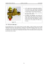
8.1.2
Complete cleaning
Complete cleaning of the mist blower includes the cleaning of all interior parts, consisting of the
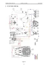
main reservoir (1 – Figure 8.1), suction filter (18 – Figure 8.1), pump (3 – Figure 8.1), pressure
regulator (14 – Figure 8.1) and nozzles (6 – Figure 8.1).
With the drain valve on the additional reservoir (16 – Figure 8.1) direct clean water towards the
suction valve (17 – Figure 8.1), which you have adjusted for drainage the additional reservoir.
Make sure to open the supply valve for the mixing nozzle (10 – Figure 8.1) on the regulator, as
well as both reservoir and strainer washing valves (23 – Figure 8.1). The flow into the main
reservoir through the pressure regulator and selector valve (9 – Figure 8.1) must be open.
After pumping the water from the rinsing reservoir, adjust the suction valve (17 – Figure 8.1) to
pumping from the main reservoir, close the selector valves (10 – Figure 8.1) on the regulator and
open the spraying sections (11 – Figure 8.1) to ensure a complete emptying of the main reservoir
through the nozzles on the spraying pipes.
8.1.3
Partial cleaning
Partial cleaning of the mist blower includes the cleaning of the suction filter (18 – Figure 8.1), the
pump (3 – Figure 8.1), the pressure regulator (14 – Figure 8.1), the distribution cube (7 – Figure
8.1) and the nozzles (6 – Figure 8.1) without changing the concentration of spray in the main
reservoir.
Move the drain valve on the additional reservoir (16 – Figure 8.1) towards the suction valve. Adjust
the direction of the suction valve (17 − Figure 8.1) to pump liquid from the additional tank
containing clean water. Using the selector valve (9 – Figure 8.1), direct the flow directly towards
the pump (3 – Figure 8.1). Make sure to close the supply valve for the mixing nozzle (10 – Figure
8.1) on the regulator, as well as both reservoir and strainer washing valves (23 – Figure 8.1). Clean
water flows through the valves (16 and 17 – Figure 8.1), the filter (18 – Figure 8.1), the pump, the
pressure regulator (14 – Figure 8.1) and open valves (11 – Figure 8.1) and finally through the
spraying nozzles. The amount of spraying agent in the main reservoir remains the same.