background image

Rev. AP12   


W2642A Quick Start Guide 

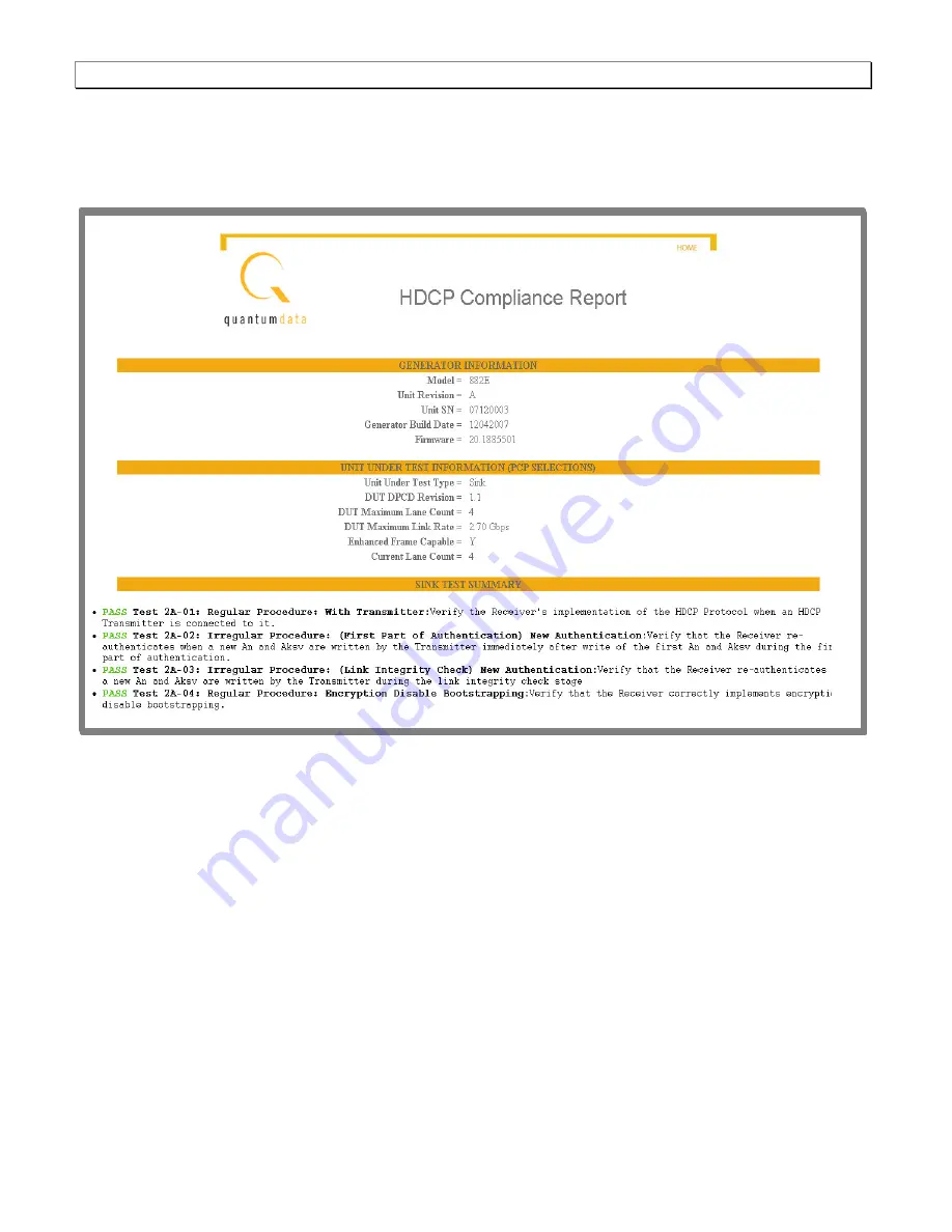
HDCP Compliance   

You can use the 882E run HDCP compliance tests on DisplayPort sink device. These tests are initiated through 
the front panel. A report is provided with a summary and detail section. A sample of the report is shown below.   


Figure 5-8 – Sample HDCP compliance test report   


Page 40 

Summary of Contents for W2642A

Page 1: ......

Page 2: ...W2642A Quick Start Guide Rev AP12 Page 1 ...

Page 3: ...ey can get the complete set of design validation and compliance test tools essential for DisplayPort product development Additional Compliance Options You can add the link layer and HDCP compliance test options to your W2642A by contacting your Quantum Data distributor Refer to Chapter 5 Application Extensions on page 32 for more details on these options The instructions provided in this Quick Sta...

Page 4: ...device to this port DISPLAYPORT AUX CHANNEL ANALYZER TO SINK connector enables you to monitor the AUX channel transactions with the Quantum Data ACA option not provided with the base W2642A A DisplayPort cable is connected from a DisplayPort display device to this port DISPLAYPORT TX connector outputs DisplayPort compatible digital video signals This connector is used when testing a DisplayPort si...

Page 5: ...d on 881 generators Front panel This subsection describes the front panel interface for operating the generator All features of the 882E not related to the AUX Channel Controller function have been disabled in the base W2642A product Therefore many of the W2642A menus for the standard 882E functions have been disabled However the administrative functions are still available You will only need to u...

Page 6: ...W2642A Quick Start Guide Rev AP12 Page 5 ...

Page 7: ...nel Controller Miscellaneous W2642A accessories Ethernet cross over cable DisplayPort cable 2 meter Adaptor Board p n 99 00607 Test workflow Testing a DisplayPort source device involves the following high level steps 1 Assemble all the test instruments devices and equipment to test in your laboratory 2 Complete the physical test setup in accordance with the test setup diagram Figure 2 1 below 3 Co...

Page 8: ...ill address the specifics of your particular test connections and configuration 10 Select Run Tests after confirming selections Test Setup The setup for testing DisplayPort source devices is shown in Figure 2 1 below For a more detailed test method please consult the U7232A Help dialog Figure 2 1 Test Setup for DisplayPort Source Tests ...

Page 9: ...et hub To connect directly you connect the Ethernet crossover cable provided between the Ethernet port on the W2642A and the PC host either the Infiniium oscilloscope or the W2642A GUI These two connection methods are illustrated in the figures below You can either connect to the W2642A over your LAN network through a hub or you can connect directly To connect over the LAN you connect a standard E...

Page 10: ...ystem menu appears on the generator s display as shown below 3 Choose the Network item by pressing the adjacent soft key The generator s IP address and subnet mask appear on the generator s display as shown below 4 Press the Settings key The Network Connection screen appears on the generator s display as shown below If the IP Address configuration option is not visible press the soft key adjacent ...

Page 11: ...o item To return to the previous screen without saving the changes choose the Back item To enable DHCP for auto IP address configuration of the generator 1 Press the Tools key The Tools menu appears on the generator s display as shown below 2 Choose the System item by pressing the adjacent soft key The System menu appears on the generator s display as shown below 3 Choose the Network item by press...

Page 12: ...anges press the Enter Options key The following choices appear on the generator s display To save the changes choose the Yes item by pressing the adjacent soft key To exit without saving the changes choose the No item To return to the Network Connection screen without saving the changes choose the Back item ...

Page 13: ...the W2642A command line Use the following procedures To enable the AUX Channel Controller function To enable the AUX Channel Controller function 1 Establish a connection to the W2642A over the Ethernet IP interface by opening up a web browser and enter the W2642A s IP address into the address entry field 1 Establish a connection to the W2642A over the Ethernet IP interface by opening up a web brow...

Page 14: ...he CMD Terminal DPTC DPTG 1 The AUX Channel Controller functionality is now enabled in the W2642A You can now connect to the W2642A with the W2642A GUI application or with the automated test applications Note Each time you reboot the W2642A you will have to enter this command if you wish to re enable the AUX Channel Control function ...

Page 15: ...isplayPort Test Point Access Adapter Miscellaneous accessories Splitters rise time converters attenuators cables as found in the DisplayPort Sink Test Method of Implementation 5989 9147EN W2642A AUX Channel Controller Miscellaneous W2642A accessories Ethernet cable DisplayPort cable 2meter Adaptor Board p n 99 00607 For Calibration of the system Agilent DSS90804A for Jitter calibration measurement...

Page 16: ... the W2642A AUX Channel Controller over the Ethernet LAN interface 7 Enable the AUX Channel Control function in the W2642A See Enabling the ACC function below Test Setup This subsection describes the test setup for testing DisplayPort Sink devices The following is an illustration of the setup for testing DisplayPort sink devices The MOI 5989 9147EN addresses the detailed requirements to greater de...

Page 17: ...W2642A and a LAN access jack or Ethernet hub To connect directly you connect the Ethernet crossover cable provided between the Ethernet port on the W2642A and the Agilent Test system These two connection methods are illustrated in the figures below You can either connect to the W2642A over your LAN network through a hub or you can connect directly To connect over the LAN you connect a standard Eth...

Page 18: ...System menu appears on the generator s display as shown below 7 Choose the Network item by pressing the adjacent soft key The generator s IP address and subnet mask appear on the generator s display as shown below 8 Press the Settings key The Network Connection screen appears on the generator s display as shown below If the IP Address configuration option is not visible press the soft key adjacent...

Page 19: ...o item To return to the previous screen without saving the changes choose the Back item To enable DHCP for auto IP address configuration of the generator 1 Press the Tools key The Tools menu appears on the generator s display as shown below 2 Choose the System item by pressing the adjacent soft key The System menu appears on the generator s display as shown below 3 Choose the Network item by press...

Page 20: ...anges press the Enter Options key The following choices appear on the generator s display To save the changes choose the Yes item by pressing the adjacent soft key To exit without saving the changes choose the No item To return to the Network Connection screen without saving the changes choose the Back item ...

Page 21: ... also enable the function through the W2642A command line Use the following procedures To enable the AUX Channel Controller function To enable the AUX Channel Controller function 1 Establish a connection to the W2642A over the Ethernet IP interface by opening up a web browser and enter the W2642A s IP address into the address entry field 1 Establish a connection to the W2642A over the Ethernet IP ...

Page 22: ...e CMD Terminal DPTC DPTG 1 The AUX Channel Controller functionality is now enabled in the W2642A You can now connect to the W2642A with the W2642A GUI application or with the automated test applications Note You will have to re enable the AUX Channel Control function each time the W2642A is rebooted if you wish to use the W2642A GUI ...

Page 23: ... Sink connected to the W2642A Tx port Load an EDID from a file Save an EDID Write EDID values to the EEPROM of a connected display You may use the W2642A GUI to configure the W2642A with a valid EDID for testing a source DPCD Supports the following functions Read an entire DPCD or a portion of a DPCD from a display connected to the W2642A Tx port Load a DPCD from a file from your PC Save a DPCD to...

Page 24: ...ow Connecting to the W2642A The procedures below describe how to connect the W2642A to the W2642A GUI The host PC will have to be configured to the specific subnet that the W2642A is set to As an example 192 168 254 239 Use the figure below as a reference for the connection procedures To connect to the W2642A 1 Enable the AUX Channel Controller functionality in the W2642A as described in Chapters ...

Page 25: ...ticate button 5 Select the desired operating Mode and State for the DPTC Select the sink Mode radio button if you are testing a video source Select the source Mode radio button if you are testing a display 6 Select the Run State radio button Steve should capitalize it Page 24 ...

Page 26: ...ing the Auto Refresh check box Note Auto Refresh should not be activated if you are changing tabs and doing extended data transfers using the other tabs as the Aux Channel transactions may collide with each other The status bar at the bottom of the window should indicate Connect Successful Testing a device The procedures below describe how to test a DisplayPort source device with the W2642A AUX Ch...

Page 27: ...rior to the last Refresh a valid IRQ pulse was received o HPD Changed indicates that prior to the last Refresh there was at least one change in the level of the HPD signal The IRQ Pulse and HPD Changed indications are cleared every time you click Refresh This allows you to leave the test equipment unattended for an indeterminate period of time without missing the fact that an IRQ or HPD change occ...

Page 28: ...the W2642A GUI to periodically update the controls and display by enabling the Auto Refresh check box Reading and writing an EDID The procedures below describe how to read and write to an EDID from a sink device under test connected to the W2642A You may configure the W2642A with a valid DPCD when testing a DisplayPort source device To read an EDID from a device 1 Select the EDID tab on the W2642A...

Page 29: ...2 The EDID appears in the EDID Raw matrix Each functional section is shown in the additional rows in the EDID tab 3 Load an EDID from a file stored on the host PC by clicking on the Load from File activation button 4 Click on the Write to DP activation button to write the EDID out to a display device connected to the W2642A 5 You can also write to specific EDID blocks by selecting the Hardware tab...

Page 30: ...a scroll bar on the right that enables you to view the segments of the DPCD 3 If you wish to read a specific DPCD register use the DPCD IO section on the right of the DPCD tab Enter the Address and Length then click on the Read activation button to initiate the read 4 You can also read specific DCPD segments by selecting the Hardware tab and then selecting DPCD for the IO Group You then populate v...

Page 31: ...c DCPD segments by selecting the Hardware tab and selecting DCPD for the IO Group Then populate values in the Address Length and Data fields and click on the Write activation button Viewing the Transaction Log The procedures below describe how to view the transactions between the device under test and the W2642A Use the figure below as a reference for these procedures To view the transactions log ...

Page 32: ...W2642A Quick Start Guide Rev AP12 Page 31 ...

Page 33: ...Port sink devices Signal analysis for testing DisplayPort source devices DisplayPort Link Layer compliance testing for DisplayPort sources Link Layer compliance testing for DisplayPort sinks Monitoring and logging of the DisplayPort AUX Channel transactions HDCP compliance testing of DisplayPort sources future HDCP compliance testing of DisplayPort sinks These options can be purchased by contactin...

Page 34: ...e pattern library provides over 400 test patterns which scale based on the format timing selected You can change any format or image parameter on the fly through the 882E front panel You can also create your own custom formats or import bitmaps for rending A sample image is shown below Figure 5 1 SMPTEBar test pattern ...

Page 35: ...f you have the optional DisplayPort AUXiliary Channel Analyzer you can monitor the link layer transactions during the link layer compliance tests or at any time during normal operation The Sink Config window is shown below This is the window you use to configure the parameters of the test Figure 5 2 Link layer compliance configuration screen Page 34 ...

Page 36: ...W2642A Quick Start Guide Rev AP12 Page 35 The source window is shown below Figure 5 3 Link layer compliance test screen sink testing ...

Page 37: ...Rev AP12 W2642A Quick Start Guide The following is an example of a report for the Link Layer compliance test for a display Figure 5 4 Sample of a link layer compliance test report Page 36 ...

Page 38: ...ource to monitor its AUX channel transactions with a DisplayPort sink device under test Or you can have the 882E emulate a DisplayPort sink device to monitor its AUXiliary channel transactions with a DisplayPort source device under test For passive monitoring you connect two DisplayPort devices a source device and a sink device through the 882E and monitor the AUXiliary channel transactions betwee...

Page 39: ...A Quick Start Guide The illustration below depicts the setup for monitoring the link layer transactions during testing of a DisplayPort sink Figure 5 5 ACA connection setup for monitoring a DisplayPort source Page 38 ...

Page 40: ...W2642A Quick Start Guide Rev AP12 Page 39 The ACA begins the trace and displays the results in the main window as shown below Figure 5 7 Sample ACA screen of link training and EDID transactions ...

Page 41: ...se the 882E run HDCP compliance tests on DisplayPort sink device These tests are initiated through the front panel A report is provided with a summary and detail section A sample of the report is shown below Figure 5 8 Sample HDCP compliance test report Page 40 ...

Page 42: ...tual Control Panel VCP codes supported by the display The application presents the supported codes in a graphical user interface allowing you to monitor MCCS transactions and operate the display through the interface In addition you can manually execute MCCS commands through the Script pane in the interface A sample screen of the MCCS interface is shown below Figure 5 9 Sample screen for MCCS test...

Page 43: ...Rev AP12 W2642A Quick Start Guide Page 42 ...

Page 44: ......

Reviews: