


171
Appendix A. Installation and Maintenance
Optical Output
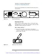
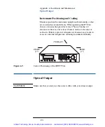
Instrument Positioning and Cooling
Mount or position the instrument upright and horizontally so that
air can circulate around it freely. When operating the E5574A,
choose a location that provides at least 75mm (3 inches) of
clearance at the rear, and at least 25mm (1 inch) of clearance at
each side. Failure to provide adequate air clearance may result in
excessive internal temperature, reducing instrument reliability.
Optical Output
C AU T I O N
Make sure that you only use the correct cables with your chosen output.
Figure A-5
Correct Positioning of the HP E5574A
25mm
(1")
25mm
(1")
75mm (3")
E5574A
OPTICAL LOSS ANALYZER
More
Head Input A
Head Input B
Optical Input
Optical Output
Active
Syst
Instr
Appl
7
4
1
0
8
5
2
•
9
6
3
+/–
Source
On/Off
Enter
Aux
Preset
Cursor/Vernier
MODIFY
E N T R Y
Help
Artisan Technology Group - Quality Instrumentation ... Guaranteed | (888) 88-SOURCE | www.artisantg.com


