


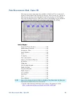


Pulse Measurements Mode - Option 330
157
Measurement Selection
The pulse measurement results are presented as either a traditional power meter
display or as a trace graph.
How to select the Measurement
Press
Measure 1
Then choose from the following:
o
Average
Average power (Meter display)
o
Peak
Peak power (Meter display)
o
Pk to Avg
Displays the difference between the above two measurements
(Meter display)
o
Trace Graph
(default) The primary trace (
Tr 1
)
plots pulse data in
amplitude versus time. Optionally, you can enable a secondary ‘zoom’ trace.
Learn how on page 158.
When a ‘Meter display’ measurement is selected, the following Pulse
Measurement Mode settings are identical to the standard USB Power Meter
Mode settings.
o
Learn how to set
Scale
on page 144.
o
Learn how to set
Relative and Offset Power
on page 146.
o
Learn how to set
Display Units
on page 146.
o
Learn how to set
Limits
on page 147.
Frequency / Time
How to set Frequency
Press
Freq/Dist
Then choose from the following:
o
Frequency
Sets the center frequency of the carrier on which pulse
modulation resides. This is used to set amplitude correction of the USB
Power Sensor.
How to set Time
Specify the time over which data will be acquired by the USB Power Sensor.
When Trace Graph is selected,
Tr 1
is annotated with these values. Time can be
specified using either of the following pairs of values:
o
Center 1
and
Time/div 1
Specify the center time and time per division.
o
Start Time
and
Time Length
Specify the start time and length of
acquisition.
o
A positive start time indicates a delay after the sensor detects a pulse signal.
o
A negative start time displays data that is acquired BEFORE the sensor
detects a pulse signal (or T-zero).
Follow each by entering a value using the numeric keypad, the
▲|▼
arrows, or
the rotary knob.


