


104
FieldFox User’s Guide
FFT Gating (Opt 238)
Time-gated spectrum analysis allows you to obtain spectral information about
signals occupying the same part of the frequency spectrum that are separated in
the time domain. Using an external trigger signal to coordinate the separation of
these signals, you can perform the following operations:
Measure any one of several signals separated in time; for example, you can
separate the spectra of two radios time-sharing a single frequency.
Measure the spectrum of a signal in one time slot of a TDMA system.
Exclude the spectrum of interfering signals, such as periodic pulse edge
transients that exist for only a limited time.
FFT Gating is a simple, efficient way to set the proper amount of trigger delay
and capture time so that signal artifacts of a repeating waveform or pulse can be
examined in the frequency domain. Learn more about trigger settings on page
100.
For best results, Auto Trigger should be used with this feature to ensure that the
sweep does not wait indefinitely for a trigger. Set Auto Trigger to a time that is
longer than the expected periodic rate of the signal. This is especially important
when using RF Burst or Video triggering in wider spans, because the signal
providing those triggers has limited bandwidth. Learn more about Auto trigger
on page 102.
For more conceptual information on this topic, please refer to Spectrum Analysis
Basics (App Note 150) at
http://cp.literature.agilent.com/litweb/pdf/5952-
pages 38-42.
How to set FFT Gating
Create a non-zero span measurement. Wider frequency spans take more time
to acquire.
Press
Sweep 3
Then
Trigger Settings
Then
FFT Gating Setup
Then choose from the following:
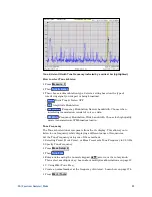
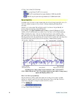
o
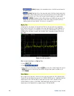
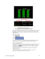
Gate View OFF ON
When ON, a separate zero span measurement is
displayed below the non-zero span window. The gate view measurement
helps to configure the gate width and delay by revealing (with green
markers) the location of the gate relative to the trigger event. The zero span
measurement is tuned to the center frequency of the non-zero span
measurement with about 5 MHz of bandwidth. The Y-axis scale is the same
for both windows.
o
Gate View Time
Set the X-axis span for the non-zero span window. Enter a
value using the numeric keypad, the
▲|▼
arrows, or the rotary knob. This
value is annotated as
Swp (nn)
below the window.
o
FFT Gating OFF ON
When ON, the trigger type, gate width, and delay are
applied to the non-zero span measurement. The Res BW is set to a value that
is inversely proportional to the gate width.


