88
6
Working with Automatic Test Systems
Limit Test
Limit Test
This section describes how to define the limit lines and determine pass or fail with regard
to the limit test function. For more on the concept of the limit test, refer to the Chapter
describing “Data Analysis and Result Output” in the User’s Guide.
Using Commands to define Limit Lines
You can define the limit lines by specifying any limit value to the parameter of SCPI
commands.
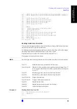
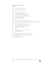
The program is described in detail below:
Line 120
Define the data array (variable) for the limit lines.
Line 170 to 240
When bit 4 of the operation status condition register changes from “1”
to “0” (negative transition), bit 4 of the operation status event register
is set to “1”.
Line 260 to 280
Set the upper and lower limit values for the limit lines in the array.
Line 310 to 320
Specify the segment number for the upper and lower limit values.
Line 330 to 340
Specify the upper and lower limit values on the trace.
Line 360 to 400
Trigger the instrument.
Line 420 to 450
It repeats to the measurement end.
Line 460
Display the limit lines.
Line 470
Display the determination result. (For fail only.)
Line 480
Activate the limit test function.
Example 6-2
Using Commands to define Limit Lines
110 DIM Buff$[9]
120 REAL Udata(1:8),Ldata(1:4)
130 INTEGER St
140 !
150 ASSIGN @Agte5052 TO 717
160 !
170 OUTPUT @Agte5052;"*ESE 60"
180 OUTPUT @Agte5052;"*SRE 32"
190 OUTPUT @Agte5052;":STAT:OPER:PRT 0"
200 OUTPUT @Agte5052;":STAT:OPER:NTR 16"
210 OUTPUT @Agte5052;":STAT:OPER:ENAB 16"
220 OUTPUT @Agte5052;"*CLS"
230 OUTPUT @Agte5052;"*OPC?"
240 ENTER @Agte5052;Buff$
250 !
260 READ Udata(*), Ldata(*)
270 DATA 0,1.4E+9,2.E-5,1.4E+9,2.E-5,1.6E+9,1.E-4,1.6E+9
280 DATA 0,1.2E+9,1.E-4,1.2E+9
290 !
300 OUTPUT @Agte5052;":DISP:WIND:ACT FP1"
310 OUTPUT @Agte5052;":CALC:FP:TRAC:LIM:UPP:SEGM:COUN 2"
320 OUTPUT @Agte5052;":CALC:FP:TRAC:LIM:LOW:SEGM:COUN 1"
Summary of Contents for E5052A
Page 4: ...4 ...
Page 28: ...28 1 Making Effective Use of This Manual How to Use This Manual ...
Page 51: ...3 51 Making a Measurement Trigger System 3 Making a Measurement Figure 3 1 Trigger system ...
Page 58: ...58 3 Making a Measurement Waiting for End of measurement ...
Page 76: ...76 4 Reading Writing Measurement Data Entering Data in a Trace ...
Page 82: ...82 Chapter5 Saving and Recalling File Management Managing Files ...


