


253
3
English URL
www.agilent.com/find/products
English URL
www.agilent.com/find/products
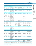
4339B
High-Resistance Meter
LCR & Resistance Meters
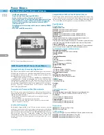
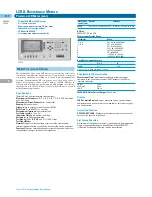
4339B High-Resistance Meter
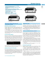
The 4339B high-resistance meter is Agilent Technologies’ most
advanced tool for making precision high-resistance measurements.
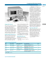
Precise and Stable Measurement
The measurement range is from 1 x 10
3
Ω
to 1.6 x 10
16
Ω
, with a basic
accuracy of 0.6%. This wide range allows accurate, high-resistance
measurement of capacitors, relays, switches, connectors, materials,
cables, and PC boards. The grounded device-under-test (DUT) mea-
surement capability of the 4339B gives you the ability to evaluate
cables and transformers under grounded conditions. The 16008B
resistivity cell and the 16339A component test fixture are designed for
stable and safe measurements of materials or components.
Simple Operation
The test-sequence program function allows you to control a series of
resistance measurements in a sequence (charge-measure-discharge).
You can set the charge time, measurement interval time, and number of
measurements in a sequence through the front panel. The remaining
time can be displayed when executing the sequence measurements.
Surface resistivity (
s) and volume resistivity (
v) functions can be
called to act upon measurement data. Calculated results are then
automatically displayed, saving you time and effort.
High-Test Throughput
The 10 ms measurement time, 2 ms high-speed contact check func-
tion, built-in comparator, and GPIB/handler interfaces deliver
high-speed test throughput for production environments.
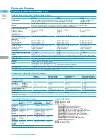
Specifications
(Refer to Technical Overview for complete specifications)
Measurement Parameters:
R (dc resistance), I (dc current),
s (surface resistivity),
v (volume resistivity)
Mathematical Functions:
Deviation and percent deviation
Display Digits:
3, 4, or 5 (selectable)
Test Voltage:
0.1 Vdc to 1000 Vdc, 0.1 V steps @ 0.1 V to 200 V, 1 V steps
@ 200 V to 1000 V
Voltage Accuracy:
(0.16% + 100 mV) @
≤
200 V,
(0.16% + 500 mV) @ >200 V
Maximum Current:
10 mA @
≤
100 V, 5 mA @
≤
250 V,
2 mA @
≤
500 V, 1 mA @
≤
1 kV
Current Compliance Setting:
0.5 mA, 1 mA, 2 mA, 5 mA, 10 mA
Output Resistance:
1 k
Ω
± 10%
Input Resistance:
1 k
Ω
± 10%
Test Cable Lengths:
2 m maximum
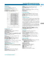
Measurement Range/Accuracy
Parameter
Measurement Range
Basic Accuracy
I
60 fA to 100 µA
±0.4%
R (
Ω
)
1 x 10
3
Ω
to 1.6 x 10
16
±0.6%
Measurement Time:
Time interval from a trigger command to the end
of measurement (EOM) signal output at the handler interface port (range:
hold, display, off)
Mode
Time (typical)
SHORT
10 ms
MEDIUM
30 ms
LONG
390 ms
Correction Function
Zero OPEN: Eliminates measurement errors due to stray parasitic
resistance in the test fixtures
Test Sequence Program:
Controls a series of resistance measurements.
Charge time, measurement internal time, and measurement number can
be programmed
Comparator Function:
HIGH/IN/LOW for the measurement parameter
Contact Check Function
Contact failure between the test fixture and device can be detected
• Available DUT Type: Capacitive DUTs only
– DUT Capacitance:
≥
1 pF + 5% of residual stray capacitance
– Residual Stray Capacitance of the Fixture:
≤
50 pF
• Additional Measurement Time for Contact Check: 2 ms
Other Functions
• Save/Recall: Ten instrument setups can be saved/recalled from
the internal nonvolatile memory
• Continuous Memory Capability: If the instrument is turned off, or
if a power failure occurs, instrument settings are automatically
memorized (
≤
72 hours at 23°C ± 5°C)
• GPIB Interface: All control settings, measured values, and
comparator information
• Handler Interface: All output signals are negative-logic, optically
isolated open collectors. Output signals include: HIGH/IN/LOW,
no contact, index, end of measurement, and alarm. Input signals
include: high voltage off, keylock, and external trigger
General Specifications
Power Requirements:
90 V to 132 V or 198 V to 264 V, 47 Hz to 66 Hz,
45 VA max.
Operating Temperature:
0°C to 45°C
Size:
100 mm H x 320 mm W x 450 mm D (3.94 in x 12.6 in x 17.72 in)
Weight:
6.5 kg (14.3 lb)
Complies with 73/23/EEC and 92/68/EEC safety standard EN61010-1
Furnished Accessories
Operation manual, shunt connector, power cable (test fixtures and/or test
leads must be ordered separately.)
Key Literature
4339B/4349B High Resistance Meters Technical Overview,
p/n 5964-6182E
Insulation Resistance Measurement of Plate Type Materials,
p/n 5968-3400E
Insulation Resistance Measurements of Electromechanical Components,
p/n 5968-0325E
Agilent Solutions for Measuring Permittivity and Permeability with LCR
Meters and Impedance Analyzers, p/n 5980-2862EN
Ordering Information
4339B
High-Resistance Meter
4339B-ABA
US-English Localization
4339B-ABJ
Japan-Japanese Localization
16339A
Component Test Fixture
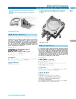
16008B
Resistivity Cell (50 mm Diameter Electrode)
16008B-001
Add 26/76 mm Diameter Electrodes
16008B-002
Add 26 mm Diameter Electrode
16117B
Low-Noise Test Leads
16117B-001
Add Pin Probes
16117B-002
Add Soldering Sockets
16117B-003
Add Alligator Clips
16117C
Low-Noise Test Leads (1 m, connectors)
16118A
Tweezer Test Fixture
• Wide measurement range: 1 x 10
3
Ω
to 1.6 x 10
16
Ω
• Stable test fixtures: resistivity cell, component test fixture
• High-speed measurement: 10 ms
• Test sequence programming
• Resistivity calculations
• Grounded DUT measurement
4339B
Summary of Contents for All
Page 1: ......


