background image


55


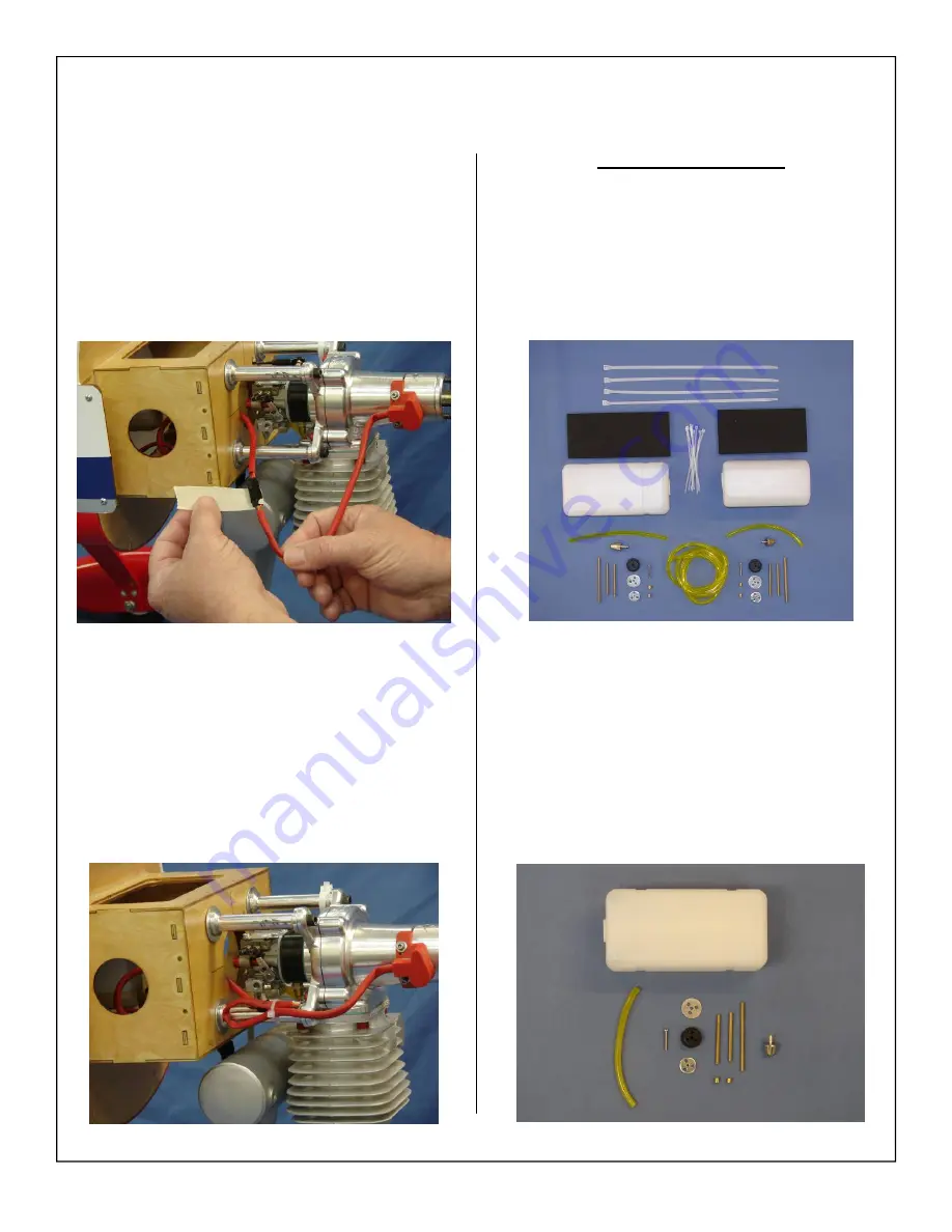
5.  Secure ignition wire with nylon ties as nec-

essary 


Fuel Tank Assembly 

 
1.  Gather the fuel tank parts as shown below. There 

are two tanks provided, 750cc (26oz) for your 
fuel system and 450cc (16oz) for your smoke 
system if used.  

4.  Route the ignition wire to the engine as shown 

and secure connectors with safety clip, tape or 
other method. 

2.  Gather the 75cc (26 ounce) fuel tank for your 

engine fuel system. 

Summary of Contents for 50cc Pitts Python ARF-QB

Page 1: ...Python ARF QB Quick Build ASSEMBLY MANUAL AEROWORKS 401 Laredo Unit D Aurora CO 80011 Phone 303 366 4205 Fax 303 366 4203 E mail info aero works net 2007 Copy write Protected All Rights Reserved by A...

Page 2: ...Tail Wire Assembly 29 Main Landing Gear and Wheel Pant Assembly 32 Tail Wheel Assembly 35 Inner Cabane and Outer Strut Installation 39 Cowl Preparation 45 Engine Muffler Throttle and Choke Installati...

Page 3: ...aterial and workmanship at the date of purchase This limited warranty does not cover any component parts damaged by use or modification In no case shall Aeroworks liability exceed the original cost of...

Page 4: ...Please read through this manual carefully before starting the assembly of your new 50cc Pitts Python ARF QB Inventory and inspect all parts and hardware for any imperfections or damage Notify Aerowor...

Page 5: ...the landing gear installed by 2 T2 6x12mm PWA screws 1 Tinted Canopy installed on the fuse by 11 T2 6x8mm PWA screws Top Wing with Aileron pre glued at factory covered 8 6 32 blind nuts installed for...

Page 6: ...s 8 3 5mm flat washers for the mounting of the outer cabane 2 1 4 20 x 2 Nylon Bolts for the bottom wing mounting 6 4 4 40 3 two end threaded pushrod with nuts and clevises for ailerons 2 4 40 4 two e...

Page 7: ...Rods R1 R3 8 Left hand thread Rods L2 L4 6 M3x20mm Phillip head bolts 6 M3 Hex nuts 4 T2 6x10mm PWA screws 16 2 5x4mm brass pull pull swaging tubes 11 1 300x300mm True Red Covering 1 300x300mm White...

Page 8: ...M recommended 1 x receiver battery min 6 0 volt 1700ma 1 x ignition battery min 4 8 volt 1700ma 2 x switches with charge jacks Tools Allen wrenches US and Metric Dremel cutting disc and sanding drum t...

Page 9: ...vering iron with a soft sock gently apply pressure and rub in the covering If any bubbles occur your iron may be to hot Reduce heat and work slowly 3 If bubbles persist use a small pin to punch holes...

Page 10: ...d color overlaps are securely sealed 3 This is an optional step but is recommended Cut strips of the supplied clear covering to fit the hinge gaps Use covering iron to seal the clear covering snugly i...

Page 11: ...G ASSEMBLY 2 Layout the servo and extension on the wing to test fit the installation and ensure servo lead is the correct length Note 180 in oz digital metal geared servos are recommended Servo select...

Page 12: ...side the wing 6 Pull servo extension through wing and pro vided exit holes in wing panel 7 Install servo in servo well with the output arm toward the leading edge of the wing Drill holes for servo mou...

Page 13: ...control horn assem bly as shown The ball link goes between the left and right sides of the control horn sides and is secured with a nylon lock nut Start with the center hole in the control horn The b...

Page 14: ...ength of the pushrod so that the servo arm is parallel to the aileron hinge line when it is placed on the servo output shaft Screw servo arm on the servo output shaft Note On metal geared servos use L...

Page 15: ...the pre cut stab slot at the rear of the fuselage 3 Center stab in fuselage 4 Align stab to bottom wing Ensure all dimen sions are equal for both left and right sides Note Ensure the stab is parallel...

Page 16: ...oth the top and bottom sides of the stab Note Use 30 minute Epoxy to allow adequate drying working time Remove any excess glue with alcohol wetted wipes 7 Double check all measurements are equal and s...

Page 17: ...uld be thinner then the thickness of the fin This will prevent any wood from showing after the fin as been glued into place 3 Using a hobby knife cut away covering to ex pose the wood at the top of th...

Page 18: ...d 6 Slide fin into position Tape or hold in place un til glue is completely cured Note Double check fin alignment before glue dries completely 7 Fin glued to fuse shown below 8 Cut two small strips fr...

Page 19: ...ying model and a model that will crash Always use brand name high quality servos 2 Assemble two control horn assemblies for the elevators as shown The ball link goes between the left and right sides o...

Page 20: ...bles 4 brass swaging tubes 4 Threaded metal RC links Not Used 4 Threaded couplers 4 4 40 ball links with mounting hardware 2 Brass Spacers 2 Control horns with mounting bolts and nuts 7 Assemble two c...

Page 21: ...by applying Vase line petroleum jelly or light oil to the hinge joint This ensures no epoxy gets into the hinge during assembly 2 Mix epoxy in mixing cup and use a tapered stick to apply the epoxy in...

Page 22: ...one side of each hinge and insert the hinge com pletely into the hole Ensure the hinge axis is vertical and parallel to the trailing edge of the fin before epoxy cures Wipe away excess epoxy with alco...

Page 23: ...tape or other method Ensure the plugs will not come apart from vibration or light tension Test fit extension length prior to installation 2 Mark and use a 1 16 bit to drill the elevator servo mountin...

Page 24: ...servo does not bind at either end point at full deflection 7 Repeat the above steps for the other stab and elevator Rudder Servo and Pull Pull Cable Installation 1 Mark and use a 1 16 bit to drill the...

Page 25: ...Brass swaging tubes 4 Locate the pre installed cable exit tubes at rear section of fuse and pass end of cable through 5 Pull the rudder cables from rear of fuse to the rudder servo tray Note Do not c...

Page 26: ...ough the brass swage tube as shown 8 Pull second loop tight against brass swage tube as shown 9 Crimp the brass tube with a crimping tool or pli ers 10 A drop of thin CA may be applied to the swage tu...

Page 27: ...s 13 Tape the rudder balance tab to the top leading edge of the vertical fin in the neutral position as shown This ensures the rudder is straight when the cables are attached 14 Screw threaded coupler...

Page 28: ...ck through the brass swage tube as shown and pull tight 16 Crimp the brass tube with a crimping tool or pli ers 17 A drop of thin CA may be applied to the swage tube to help secure the cable 18 Cut of...

Page 29: ...ing wires and mounting hardware Note Long wires fit to the top and short wires fit to the bottom section of tail 2 Install wires into pre drilled mounting holes in fin and stabilizer Note The brass tu...

Page 30: ...rass coupler and pre drilled holes in fin and stab 4 Secure mounting bolts with lock nuts 5 Top flying wire installation shown below 6 Attach bottom flying wires to bottom of fuse with mounting screws...

Page 31: ...flying wire tension until wires are taught but not to tight Overly tight wires will break easier during flight Note The brass turn buckles have left and right handed threads to make adjustments easie...

Page 32: ...nding gear mounting hardware 2 Remove bottom hatch cover 3 Fuse shown with hatch cover removed 4 Align mounting holes of main landing gear with pre drilled mounting holes in fuselage mounting plate No...

Page 33: ...on landing gear bolts before attaching the landing gear 6 Bolt landing gear strut to fuse with 4 bolts and washers 7 Gather the wheel parts as shown below 2 wheels 2 axle assemblies 4 wheel collars 8...

Page 34: ...inner wheel collar on the axle Use a drop of blue Loctite on the wheel collar set screw and secure the wheel collar in place 11 Install the wheel and outer wheel collar Use blue Loctite on the wheel c...

Page 35: ...n below Tail Wheel Installation 1 Gather the tail wheel parts shown below Tail wheel strut and leaf spring 3 tail wheel mounting screws steering tiller 2 tiller mount ing screws and 2 steering springs...

Page 36: ...s and secure in place 5 Place the tail wheel leaf spring on top of the tail wheel strut Position the tail wheel and spring on the bottom of the fuse over the pre drilled mounting holes 6 Mount the tai...

Page 37: ...using three wood screws 8 Attach the steering spring to the rudder tiller and tail wheel tiller Center the spring between both tillers 9 Use pliers to twist spring ends closed around the rudder steeri...

Page 38: ...t spring ends closed around the tail wheel tiller Note Ensure rudder is in the centered or neutral position 12 Repeat for opposite side tail wheel spring Ad just length and spring tension so that tail...

Page 39: ...into the provided slot at the rear cabane This will make for a easy and clean servo wire installation for the top wing ailerons Note There is a small slot provided for the extension to pass through 3...

Page 40: ...slot of the fuselage 6 Left Front and Rear inner cabane inserted into fuse shown below 7 Repeat cabane installation steps for other side inner cabane 8 Secure rear inner cabanes with 4 40 x 15mm bolt...

Page 41: ...e hole in radio floor of fuse 11 Secure front cabanes using 4 40 x 15mm bolts flat washers and blue Loctite 12 Gather the outer struts and mounting hardware 8 Steel L mounting brackets 8 4 40 x 15mm b...

Page 42: ...brackets into mounting slots in bottom wing 14 Install using 4 40 x 10mm bolt 6 flat washer and Blue Loctite to secure 15 Securely tighten L bracket into place 16 Place L shaped mounting brackets int...

Page 43: ...bottom wing using provided nylon 1 4 20 x 2 mounting bolts 20 Attach top wing to Inner cabane using 4 40 x 15mm bolts and 6 Bonded washers Note Bonded washers will prevent bolts from coming loose fro...

Page 44: ...ensure quick and accurate installation Note Markings may differ from picture 22 Align outer strut with aluminum L brackets and check for correct fit 23 Attach outer cabane with 4 40 x 15mm bolts and 6...

Page 45: ...piece of masking tape directly behind cowl onto fuselage COWL PREPARATION Important step DO NOT skip 2 Place another small piece of masking tape onto the cowl as shown 3 Centered on the tape draw an...

Page 46: ...HROTTLE AND CHOKE SERVO INSTALLATION 2 DA 50 with Pitts style muffler and mounting hardware shown below Note Mounting hardware is Not Supplied 2 1 2 stand offs available through Desert Aircraft 3 Loca...

Page 47: ...f the engine mounting holes on template 6 Use a 1 4 drill bit to drill the engine mounting holes 7 Align mounting template with firewall and tape in place 8 Use a 1 4 drill bit to drill the engine mou...

Page 48: ...engine box top hatch cover 11 Use blue Loctite to secure all mounting hard ware Note Using a flat fender washer behind firewall will help dispense the bolt pressure and help prevent the wood from cru...

Page 49: ...trays will not be necessary for the DA50 installation However have been supplied for alternative engine installations 2 Use a 1 4 bit to drill a pushrod exit hole in the firewall in line with the engi...

Page 50: ...ble servo arm to servo at 90 degrees to servo Drop servo into provided servo mounting slot in fuse with servo out put shaft to the rear Align throttle servo with throttle pushrod and mark servo mounti...

Page 51: ...tray 10 Install throttle servo to mounting tray 11 Remove pushrod from throttle arm on carburetor and cut throttle pushrod to length 12 Gather the soldering tools as shown below Note For best results...

Page 52: ...4 40 ball links and secure Power up the receiver and throttle servo and adjust pushrod for proper op eration Ensure the servo or rod does not bind or jam at closed or full open positions 16 A none sol...

Page 53: ...ng friction for the choke push rod Place silicon fuel tubing over the wire pushrod to prevent damage from vibration and provide holding friction Place a wheel collar on the end of the pushrod to provi...

Page 54: ...other stand offs required Ignition Module Installation 1 Gather the ignition module and installation parts as shown below 2 Insert provided Velcro strap through the pre cut slots at the engine box bo...

Page 55: ...arts as shown below There are two tanks provided 750cc 26oz for your fuel system and 450cc 16oz for your smoke system if used 4 Route the ignition wire to the engine as shown and secure connectors wit...

Page 56: ...ep the weight of the fuel clunk from pulling the fuel line off the brass tube Note No brass barbs are required for the air vent lines 4 Assemble the fuel pick up line rubber stopper and metal end caps...

Page 57: ...ithout touching the top of the tank 8 Install the fuel tubing and clunk Secure the fuel tubing with nylon ties to the pick up tube and clunk 9 Insert the rubber stopper assembly into the tank with the...

Page 58: ...ten the fuel line will help with the installation of the fuel T 13 Install the fuel filter and fuel filler line to the fuel tank Be sure to leave enough fuel line to reach the engine carburetor and th...

Page 59: ...el and smoke tanks position them side by side as shown below Fuel tank flat and smoke tank on its side 2 Thread nylon ties under tank mounting plate and center in position Install foam rubber pad for...

Page 60: ...e or when lifting the tail 6 Route fuel line through firewall and connect to the engine carburetor as shown Use nylon tie to secure Filler Dot and Vent Exit Line Installation 1 Gather the fuel filler...

Page 61: ...line through to give a finished professional look 5 Determine the vent line hole location at the bot tom fuse hatch cover Mark and drill a hole and install the fuel line rubber grommet The rubber grom...

Page 62: ...62 6 Drill hole in bottom hatch cover to accommo date rubber gourmet 7 Feed vent line tubing through the rubber grom met in the hatch cover 8 Install fuse bottom hatch...

Page 63: ...e chose to mount the ignition switch on the same side as the fuel filler on the left side Switch mounting location is at builders discre tion Mark the location for the ignition switch using the switch...

Page 64: ...ecommend mounting the receiver switch on the opposite side of the fuselage 6 Mount ignition regulator as desired Secure all connectors with tape safety clip or similar 7 Insert Velcro straps into moun...

Page 65: ...Mount receiver battery and receiver regulator using the same steps and techniques as for the ignition 11 Attach Y Harness to the servo extension for the top wing 12 Secure Y Harness with tape or safet...

Page 66: ...er 14 Install the receiver antenna in the pre mounted antenna tube Note Placing baby powder on the antenna will aid in sliding it through the tube 15 Place tape on the antenna and tube this will keep...

Page 67: ...obby Knife Ruler Tape Felt tip pen or marker Template material has been supplied COWL INSTALLATION 2 Mark a center line down one side of the template material 3 Center line drawn on template shown bel...

Page 68: ...6 Remove muffler to make easier installation of the cowl template 7 Align center line on template with center mark on tape you installed before the engine installa tion steps 8 Align 3 8 mark across t...

Page 69: ...the template in the same loca tion Note Mark Cowl Side on template for easy reference when placing template on cowling 11 Remove the template Using a hobby knife cut around the lines you just created...

Page 70: ...Rear Edge of the template 14 On 1 1 4 marks draw a reference line across the Rear of the template 15 Measure and mark 3 1 4 from the center line of template as shown 16 Measure and mark 2 1 2 from the...

Page 71: ...template as shown below Note Relief hole is offset on template to match offset of engine and muffler Always double check your work 19 Draw joining lines from the cylinder head cut out to the front of...

Page 72: ...pen lines 23 Remove the template and use a rotary cutting tool and sanding drum to cut out the opening in the cowl 24 Reinstall the cowl to check the fit of the cylinder head and muffler Note Be sure...

Page 73: ...g for the DA 50 Depending on your engine s operating temperature you may need to allow for more inlet air for your engine to run at its recommended operating temperature Always check the operating tem...

Page 74: ...plate into position aligning the cutouts of front plate over the ring of dummy radial engine 5 Place bolt and washer through front jig plate and screw into blind nut in jig back plate Hand tighten on...

Page 75: ...nce satisfied with the location of the dummy radial tighten the jig bolt firmly into place 8 Gather Thick CA glue and a good quality Sili cone glue Note We recommend Zap all purpose adhesive for best...

Page 76: ...ngine cylinder head Note Always check the operating temperature of your engine to prevent any damage from occurring Aeroworks is not responsible for damages incurred from improper engine cooling 13 Co...

Page 77: ...77 1 Factory placement of decals shown DECAL INSTALLATION Decals Available through Aeroworks 2 Factory placement of decals shown...

Page 78: ...ac Also a solution of 1 drop of dish detergent to a cup of water sprayed on the model will as sist in proper positioning Note Clean surface and tighten all covering before any decals are applied 2 Cut...

Page 79: ...ransfer tape to top of decal 6 Peel backing from decal 7 Spray model surface with application fluid Windex or soapy water solution 8 Spray back side of decal with application fluid Windex or soapy wat...

Page 80: ...ecal smooth and remove all excess application fluid Let decal set until dry enough to be able to remove transfer tape with out removing decal Do not leave until completely dry or transfer tape will be...

Page 81: ...and centered on bottom decal Press top decal onto bottom decal and squeegee out excess application fluid Let decal dry until transfer tape can be lifted without removing decal 16 Finished decal insta...

Page 82: ...g to manufactures recommend installation procedure DASH AND PILOT INSTALLATION Available Through Aeroworks 3 Reattach canopy using mounting screws 1 If installing pilot or dash remove canopy mount ing...

Page 83: ...s cowl from cracking and to prevent mounting bolts from loosing from normal engine vibration PRE FLIGHT PREPARATION 2 Connect aileron extensions to aileron servos in bottom wing 3 Secure extension wit...

Page 84: ...gine vibration and flying 6 Secure outer cabanes with 6 32 x 15mm bolts flat washer and lock nut 7 Ensure lock nuts are tight and will not come lose from engine vibration 8 We recommend using Velcro h...

Page 85: ...e rear inner cabane and to the side of the safety clip 10 Secure safety clip to the cabane with Velcro 11 This will give you a simple and virtually invisi ble method for connecting the top wing ailero...

Page 86: ...CG to ward the tail Move the battery or add small stick on weights to the nose or tail as necessary 4 For aerobatic flying a more aft balance point is better For smooth sport flying a more forward CG...

Page 87: ...the aileron throw in inches CONTROL THROWS 3 Use the widest part of the elevator as shown to measure the elevator throw in inches 4 Measure the rudder deflection in inches from the rudder boost tab No...

Page 88: ...re Elevator throw in degrees 8 Gather the Rudder Throw Meter Supplied and scotch tape 9 Slide the throw meter under the rudder boost tab 10 Center the throw meter on the rudder using the centering mar...

Page 89: ...89 11 Bend the precut positioning tabs down around the fin 12 Secure the tabs to the fin using scotch tape As shown below 13 Degrees are measured at the tip of the boost tab as shown below...

Page 90: ...ngine Flight Controls Ensure all flight controls are free from binding and are centered Check that all hinges are tight and will not pull out Control linkages must be rigid and tight and have no slop...

Page 91: ...er you can think of Here is a list of some of the more popular aerobatic and 3D maneuvers you can try Loops and rolls Knife edge flight Stall turns Snap rolls 2 4 and 8 point rolls Slow rolls Spins up...

Page 92: ...___ ___________________________________________________________________________ ___________________________________________________________________________ ____________________________________________...

Reviews: