


Installation and Configuration
Ndrive HP 10/20/30 Manual
2-12
www.aerotech.com
2.5.2. DC Brush Motor with Tachometer Feedback Configuration
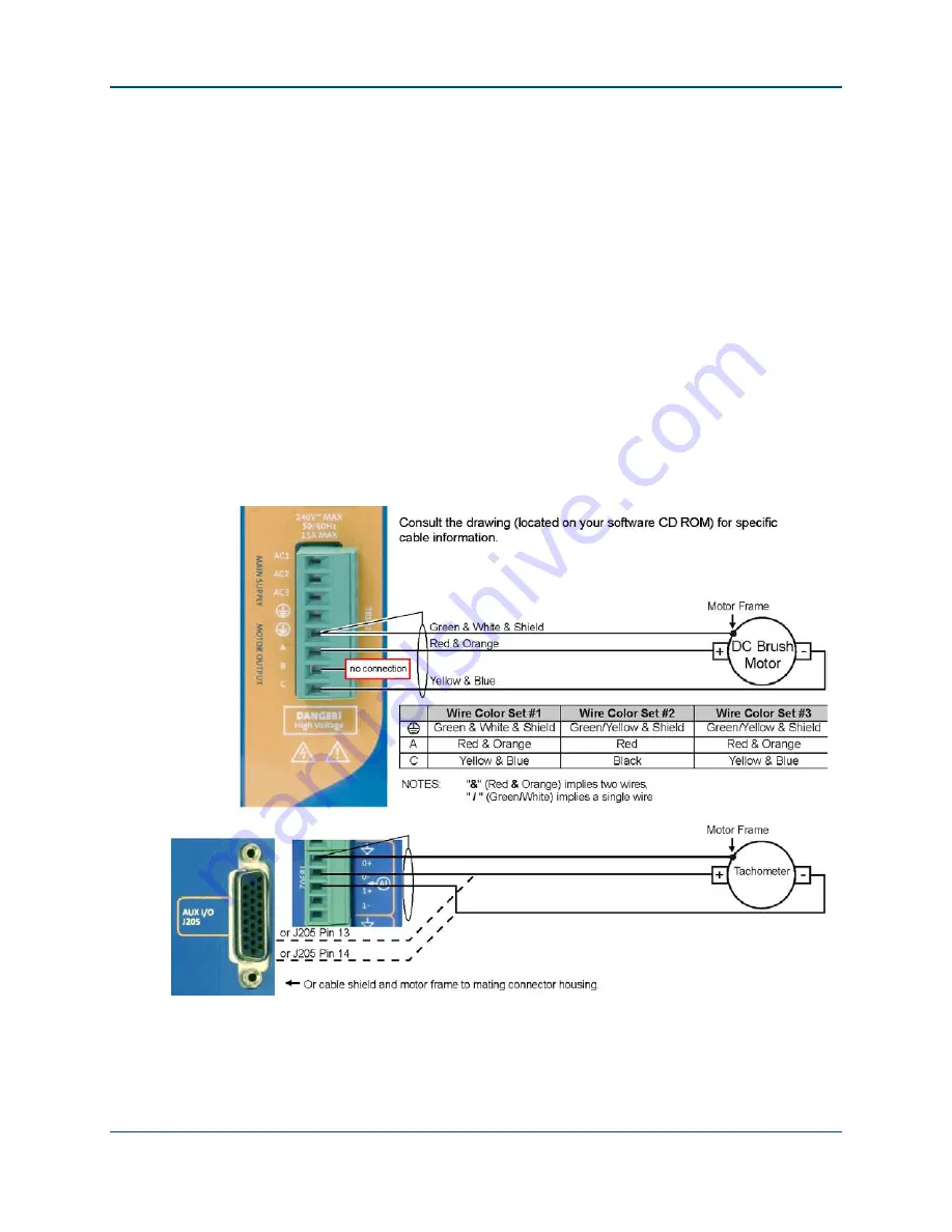
The DC brush motor configuration is shown in Figure 2-10. See section 2.6.1 for the
correct encoder phasing information if Aerotech’s standard cabling is not used. The
tachometer may be connected to TB302 or J205 as shown in the picture below. Note, that
tachometer feedback uses analog input 0, so it may not be used when tachometer
feedback is used. To configure the axis parameters in this mode, see the "Brush Motors
in Velocity Mode" topic in the Nview HMI help.
The analog input that the tachometer is connected to is scaled for ± 10V input maximum.
The tachometer voltage must not exceed ± 10 volts or the velocity loop will become
unstable, possible causing a runaway condition. Based upon the tachometer voltage
rating, a resistor-scaling network may be required to limit the tachometer voltage to ±
10V at maximum speed. If noise is present on the tachometer signal, a high quality 1 uF
capacitor may be required across the tachometer leads, before any voltage divider,
required to limit the maximum input voltage to the analog input.
The motor and tachometer are correctly phased, when rotated clockwise by hand and the
tachometer generates a positive voltage as displayed on analog input 0 and the motors
back EMF generates a negative voltage at motor terminal A (with the voltmeter common
probe at motor terminal C).
Figure 2-10.
DC Brush Motor Wiring with Tachometer
Artisan Technology Group - Quality Instrumentation ... Guaranteed | (888) 88-SOURCE | www.artisantg.com


