


OPTION 008 RF PROFILES AND COMPLEX SWEEP
Annex-B-7
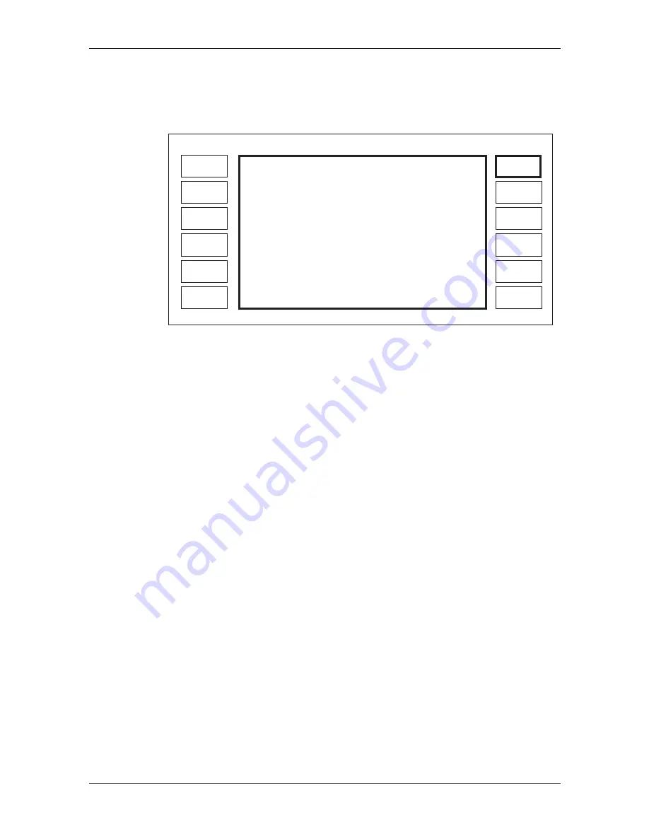
Creating a profile
An RF profile editor is provided to create or edit profiles. The instrument must be unlocked to
Level 1 in order to use the editor. To use the profile editor press the
[Edit Profile]
key to give the
display shown in Fig. B-6.
Profile
Level
Next
Point
Previous
Point
Carrier
Freq.
LOCAL
Recall
Profile
Erase
Profile
Store
Profile
Remove
Point
EXIT
Carrier:
Freq.
Relative:
Level
Ref0.0 dBm
Cal. Points in Profile:
0
Offset: +0.0 dB
RF Profile Editor
C0866
10.0000 0000
+0.0
MHz
dB
Fig. B-6 RF profile editor menu
The RF offset will only be displayed if an offset value has been selected and enabled. The signal
generator's RF level setting is displayed as the reference level.
If the user wishes to edit an existing profile, pressing
[Recall Profile]
followed by the profile
number (0 to 9) and the [enter]
key will recall a profile into the editor. A profile can be erased by
pressing
[Erase Profile]
followed by the profile number (0 to 9) and the [enter]
key.
Profiles are constructed by entering the carrier frequency at which a correction is to be applied and
then adjusting the RF output level until the required setting is obtained. The relative level shows
how much the RF level has been adjusted from its nominal value. A positive value of relative
level increases the RF output level.
To construct a profile first select the required carrier frequency using the
[Carrier Freq
.
]
key. The
relative level at that frequency can then be adjusted by pressing
[Profile Level]
. The carrier
frequency or profile level can be entered using the keyboard or the rotary control.
When the required value of level has been set up the point is saved using the
[Save Point]
key
which appears in place of the
[Remove Point]
key. The
Cal Points in Profile
display shows how
many points form the profile (a profile can have up to 100 points).
When a profile has been constructed (or is being entered) the points can be inspected by using the
[Next Point]
or
[Previous Point]
keys. To make the user aware that a limit has been reached i.e.
the first or last point in a profile, the message
At Top Limit
or
At Bottom Limit
is displayed at the
top of the screen. Points can be deleted using the
[Remove Point]
key. When
[Remove Point]
has
been pressed, an additional key
[Restore Point]
appears. This allows a point which has been
accidentally removed to be reinserted.
Points can be added to the profile in any frequency order so that if, for instance, it is found
necessary to add a point between two existing points, then when the point is saved the software
automatically re-orders the points into an ascending frequency order, and provides interpolation
between these points.
Hint:
The rotary control provides a very useful means of editing or creating a profile. If the control is
used to adjust carrier frequency while the power at a remote point is monitored, the control gives a
good feel for where points should be inserted. The interpolation of the correction data between
frequencies results in the most useful location for correction points to be either at or at either side
of maximum or minimum values of power.