FORM NO. 56043096 - Captor
™
4300B, 4800B -
27
HOPPER SYSTEM
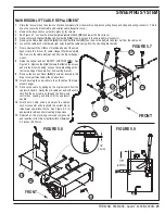
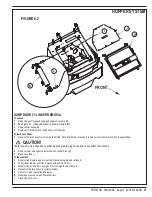
DUMP DOOR CYLINDER REMOVAL
To access:
1
Raise Hopper Cover and engage hopper cover prop rod.
2
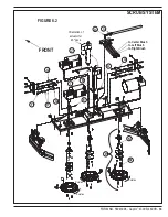
See Figure 6.2. Raise and support Shaker Assembly
(H)
.
3
Remove filter assembly.
4
Remove (11) Bolts
(I)
and remove Access Panel
(J)
.
To remove cylinder:
1
Remove the two hoses from Door Cylinder
(K)
. Note: Mark hose locations to insure correct connections when reassembling.
CAUTION!
There may be oil in hoses and cylinder, be prepared to plug hoses and cap cylinder connections.
2
Remove lower and upper cotter pins and Cylinder Pins
(L)
.
3
Remove cylinder.
To reassemble:
1
Mount cylinder end to upper mounting bracket using pin and cotter pin.
2
Pull cylinder rod out until clevis meets with dump door arm.
3
Mount cylinder rod end to dump door arm using pin and cotter pin.
4
Reconnect the two hoses in correct position.
5
Check for proper operation and leaks.
6
Reinstall access cover and filter assembly.
7
Close Hopper Cover.
FIGURE 6.2
Summary of Contents for 56303000
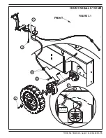
Page 17: ...FORM NO 56043096 Captor 4300B 4800B 15 FRONT WHEEL SYSTEM FIGURE 3 1...
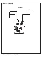
Page 20: ...18 FORM NO 56043096 Captor 4300B 4800B HYDRAULIC SYSTEM FIGURE 4 3...
Page 33: ...FORM NO 56043096 Captor 4300B 4800B 31 SOLUTION SYSTEM FIGURE 7 1...
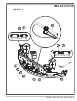
Page 39: ...FORM NO 56043096 Captor 4300B 4800B 37 SQUEEGEE SYSTEM FIGURE 10 1...
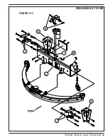
Page 41: ...FORM NO 56043096 Captor 4300B 4800B 39 SQUEEGEE SYSTEM FIGURE 10 2...
Page 45: ...FORM NO 56043096 Captor 4300B 4800B 43 WIRING SCHEMATIC before SN 1767238 ELECTRICAL SYSTEM...
Page 50: ......


