FORM NO. 56043096 - Captor
™
4300B, 4800B -
11
WHEEL DRIVE SYSTEM
GEARBOX REMOVAL
1
Follow the steps of the
Wheel Drive Motor Removal
section.
2
Drain the gearbox oil see
Gearbox Drain and Fill
instructions.
3
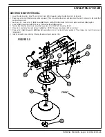
See Figure 1.3. Remove the (4) steering shaft cover screws and (6)
(J)
Floor Plate (Chain Cover) screws then remove both covers together.
4
Loosen the 4
(K)
Bolts that secure the chain idler sprockets assembly to the floor. Loosen the Lock Nut
(L)
on the idler tension adjustment bolt
which then will release the chain tension.
5
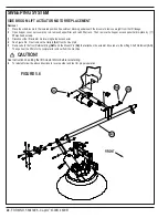
See Figure 2.1. Remove the 4
(M)
Bolts that fasten the Chain Cover Plate and Steering Plate to the Gearbox. Remove the Chain Cover Plate
by rotating the Plate to slide over the motor bolt heads to access the Steering Chain Links.
6
Remove both master links securing the steering chain at the Steering Plate
(N)
then remove the chain.
7
Remove the (4)
(G)
Steering Clamps from the Steering Plate
(N)
, then remove the Steering Plate by aligning the internal notches to clear the
motor.
8
Rotate the drive/steer tire so that it is 90 degrees (perpendicular to the frame) then block the front wheels.
9
Remove the (6)
(H)
Gearbox Mounting Bolts. Note: Use an 18-mm socket.
10
Safely jack up or lift the rear of the machine to remove the motor/gearbox assembly by carefully guiding it down through the bottom of the frame
opening.
WARNING!
Never work under a machine without safety stands or blocks to support the machine.
11
Rest the tire on the floor and tilt the top of the motor away from the wheel and roll out the opposite side.
NOTE:
The motor is heavy, block or
strap motor to assist when removing.
Installation
1 NOTE:
Refer to the
Gearbox Drain and Fill
section.
2
Raise the rear of the frame high enough to clear the Gearbox. Then position the gearbox assembly with the drive tire installed underneath the
machine.
3
Tilt and support the gearbox assembly into position at the chassis opening and slowly lower the machine to align the (6) threaded gearbox
mounting holes with the (6) holes in the chassis.
4
Fill Gearbox with oil see Gearbox Drain and Fill instructions.
5
Apply loctite 242 (blue) to the threads of the (6)
(H)
Gear Box Mounting Bolts, then install and torque to 59 ft/lbs.
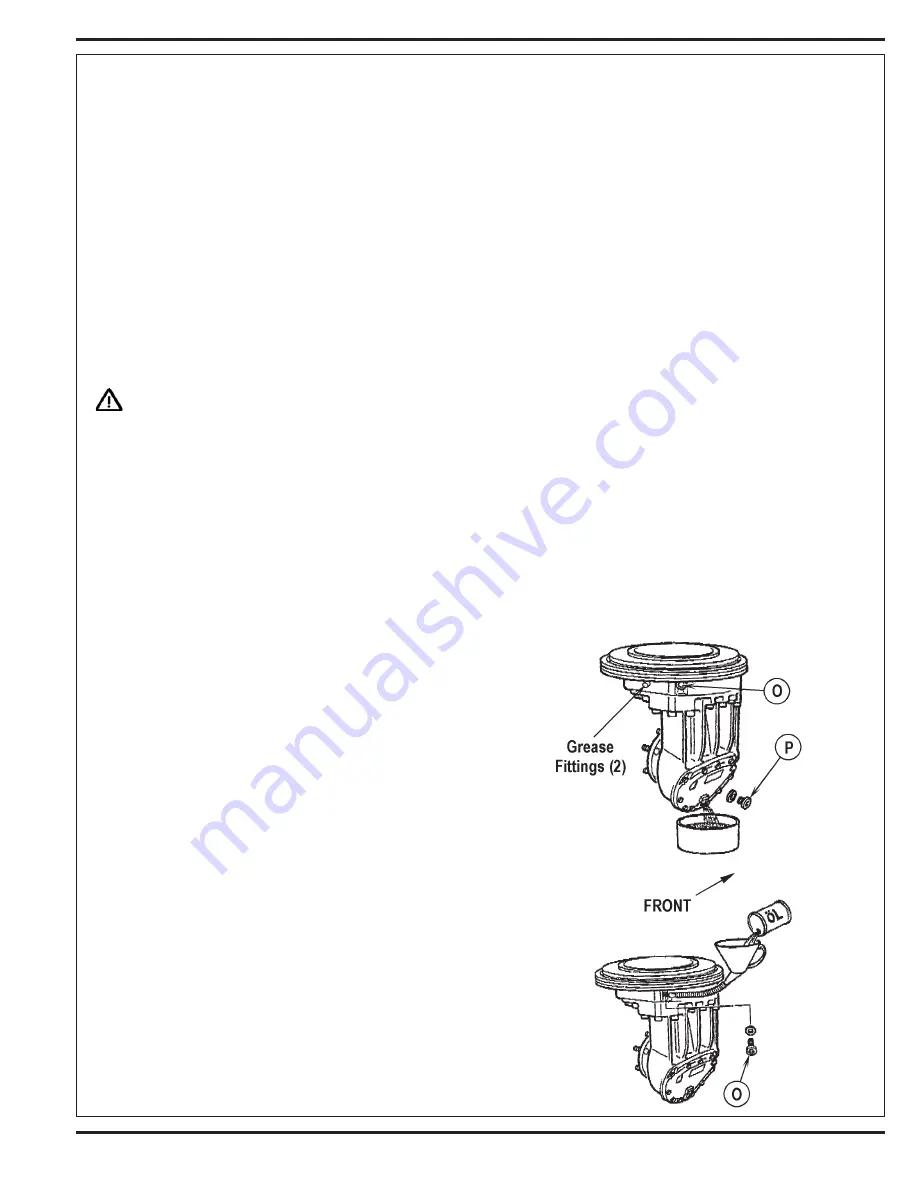
GEARBOX DRAIN AND FILL
Gearbox (transmission) oil specification
Type:
SAE 80-90, API GL4 OR MIL L2105
Qty:
2.8 qts. (2.7 L)
1
See Figure 2.2. Remove the Oil Filler Plug
(O)
using a
6mm Allen wrench.
2
Remove the Oil Drain Plug
(P)
with the same Allen
wrench.
3
Collect the oil in a drain pan, this will take approximately
5 minutes.
4
Clean the magnet in the Drain Plug
(P)
and re-install the
plug, torque to 16 ft/lbs.
5
Re-fill the gearbox with the proper gear lube.
6 NOTE:
If the gearbox is in the machine, the wheel drive
motor will have to be removed to re-fill the gearbox
(refer to the
Wheel Drive Motor Removal
section). If the
gearbox is outside the machine you can re-fill through
the Oil Filler Plug hole
(O)
using a funnel and hose 1/2”
(13 mm) in diameter. Fill until the lube just begins to
come out through the filler hole.
7
Re-install the Oil Filler Plug
(O)
and torque to 16 ft/lbs.
FIGURE 2.2
Summary of Contents for 56303000
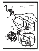
Page 17: ...FORM NO 56043096 Captor 4300B 4800B 15 FRONT WHEEL SYSTEM FIGURE 3 1...
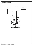
Page 20: ...18 FORM NO 56043096 Captor 4300B 4800B HYDRAULIC SYSTEM FIGURE 4 3...
Page 33: ...FORM NO 56043096 Captor 4300B 4800B 31 SOLUTION SYSTEM FIGURE 7 1...
Page 39: ...FORM NO 56043096 Captor 4300B 4800B 37 SQUEEGEE SYSTEM FIGURE 10 1...
Page 41: ...FORM NO 56043096 Captor 4300B 4800B 39 SQUEEGEE SYSTEM FIGURE 10 2...
Page 45: ...FORM NO 56043096 Captor 4300B 4800B 43 WIRING SCHEMATIC before SN 1767238 ELECTRICAL SYSTEM...
Page 50: ......


