FORM NO. 56043096 - Captor
™
4300B, 4800B -
21
SWEEPING SYSTEM
MAIN SWEEPING BROOM MOTOR REMOVAL
WARNING!
Disconnect the battery Pack using the emergency disconnect knob
(KK)
before servicing.
1
Drain and remove the recovery tank then remove the top broom motor frame access cover fastened with two screws.
2
Follow the instructions in this manual section for the removal of the main broom belt. It must be removed first to access the inner broom motor
belts.
3
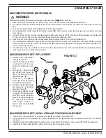
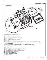
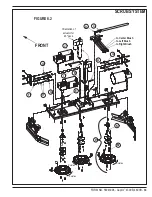
See Figure 5.2. Remove the (4) Screws
(S)
that fasten the rear Belt Guard
(T)
.
4
From underneath the machine loosen the belt tensioner Locknut
(W)
. Then loosen the (4) item
(H)
Hex Screws that secure the broom motor
to the chassis.
5
Next lower the broom motor by turning the adjustment Screw
(X)
counter clockwise (CCW) to shorten the distance between the (2) pulleys
(I
&
R)
. Then remove (roll off) the (2) broom motor Belts
(Y)
using the end of a screwdriver shaft.
6
Remove the Hex Screw
(U)
that secures the Belt Sheave Assembly
(R)
then slide it off from the Shaft Weldment
(V)
.
7
From underneath the machine first mark and then disconnect the broom motor wiring. Then remove the (4) Hex screws
(H)
that secure the
broom motor and carefully slide it out from the machine’s side frame opening. Note: Support the motor properly to prevent any damage to the
motor’s electrical terminal studs.
8
Follow the above steps and re-install the motor in reverse order. See the broom motor and broom belt installation and tensioning instructions
in this manual section to re-tension both sets of belts.
MAIN BROOM DRIVE BELT REPLACEMENT
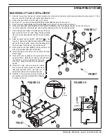
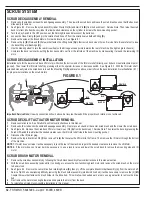
FIGURE 5.3
1
Disconnect the battery before
servicing the machine.
2
Have the main broom in its raised
stored position and then open
the left side main broom access
door.
3
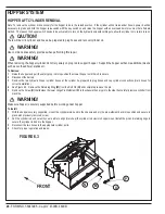
See Figure 5.3. Remove the (6)
item
(J)
Belt Cover Screws as
shown. Then remove the Cover
(K)
and Belt Shield
(L)
.
4
Loosen the (2) item
(M)
Hex
Screws that secure the movable
belt tensioner Weldment
(N)
.
5
Next loosen the item
(O)
Lock-Nut
that secures the belt tensioning
adjustment Screw
(P)
.
6
Then back-out, unthread counter
clockwise (CCW) the adjustment
Screw
(P)
to shorten the distance
between the two pulleys
(Q
and
R)
. Then use a small diameter
round shafted screwdriver to
assist in rolling the (2) Belts
(Z)
off the pulleys.
MAIN BROOM DRIVE BELT INSTALLATION AND TENSIONING ADJUSTMENT
1
It is important to replace both belts as a matched set so that the belt tension is the same for both.
2
Roll two new belts onto the Pulleys
(Q
and
R)
. Then turn the adjustment Screw
(P)
clockwise (CW) to increase the belt tension to 1/8” deflection
at mid point.
3
Tighten the (2) Hex Screws
(M)
securing the belt tensioner and then tighten the adjustment screw Lock-Nut
(O)
to finish the adjustment.
4
Reinstall the belt guard and shield then test the main broom system for its proper operation.
Summary of Contents for 56303000
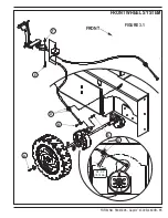
Page 17: ...FORM NO 56043096 Captor 4300B 4800B 15 FRONT WHEEL SYSTEM FIGURE 3 1...
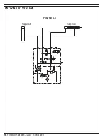
Page 20: ...18 FORM NO 56043096 Captor 4300B 4800B HYDRAULIC SYSTEM FIGURE 4 3...
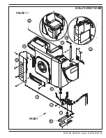
Page 33: ...FORM NO 56043096 Captor 4300B 4800B 31 SOLUTION SYSTEM FIGURE 7 1...
Page 39: ...FORM NO 56043096 Captor 4300B 4800B 37 SQUEEGEE SYSTEM FIGURE 10 1...
Page 41: ...FORM NO 56043096 Captor 4300B 4800B 39 SQUEEGEE SYSTEM FIGURE 10 2...
Page 45: ...FORM NO 56043096 Captor 4300B 4800B 43 WIRING SCHEMATIC before SN 1767238 ELECTRICAL SYSTEM...
Page 50: ......


