FORM NO. 56043096 - Captor
™
4300B, 4800B -
17
HYDRAULIC SYSTEM
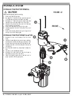
HYDRAULIC PUMP REMOVAL
(WHEN HOPPER CAN BE RAISED WITH THE PUMP OR EXTERNAL MEANS)
Note: If raising the hopper without the pump operating you must have the key on and hopper up switch activated while raising the hopper. This will
allow movement of the hopper cylinder by returning the oil back to the reservoir.
HYDRAULIC PUMP REMOVAL
(WHEN HOPPER CANNOT BE RAISED WITH THE PUMP OR EXTERNAL MEANS)
1
Disconnect the battery by using the Emergency Disconnect Knob
(KK)
.
2
Remove right side battery panel.
3
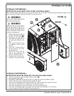
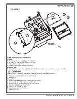
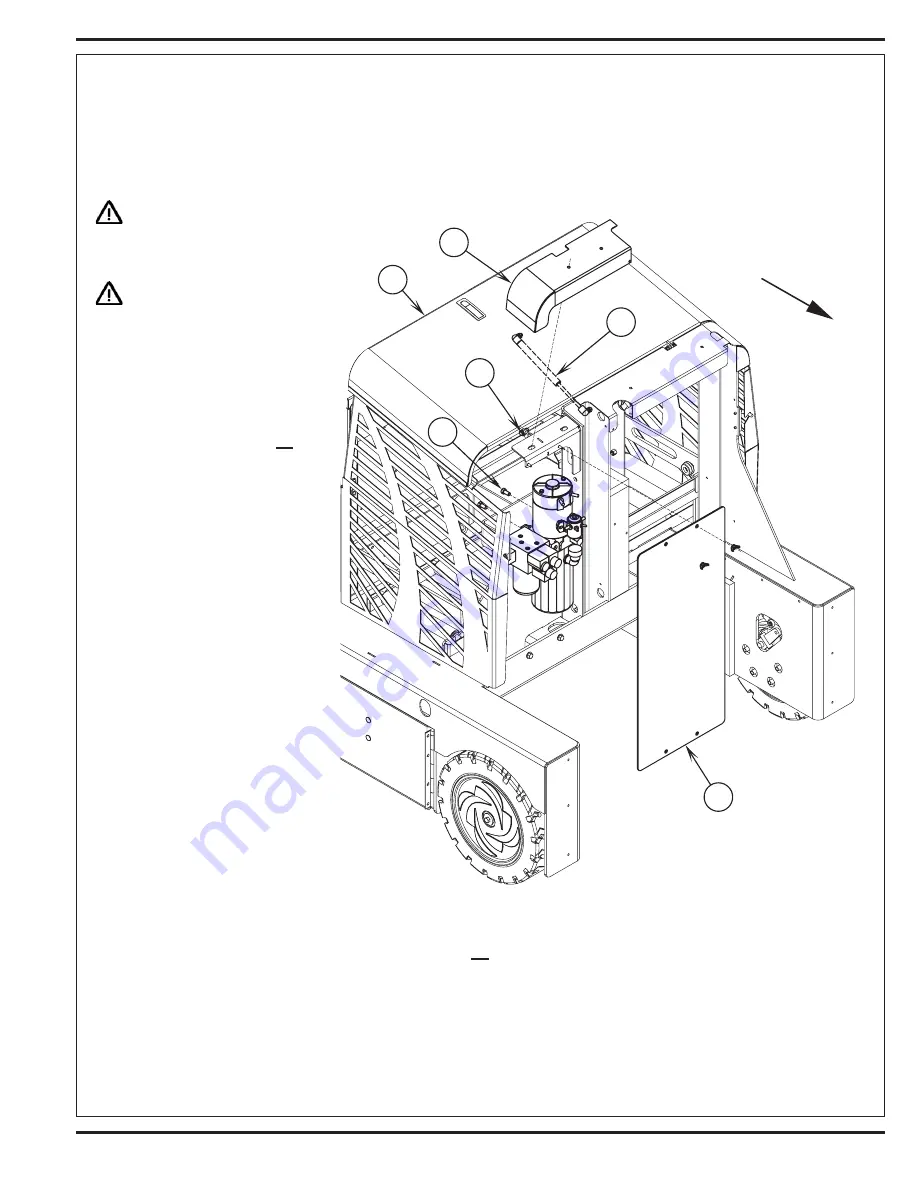
See Figure 4.2. Remove the top right side Cosmetic Cover
(A)
and pump assembly Rubber Cover
(B)
.
4
Disconnect the battery cover assembly Gas Cylinder
(J)
from the chassis.
5
Remove the 2 Screws
(K)
and nuts that fasten the Battery Cover
(L)
to the chassis and then remove the cover.
6
Remove all motor wiring and save for reinstallation on the new pump assembly.
7
Remove the 4 hydraulic hoses at the pump assemble. Note mark, cap and plug hoses.
8
Remove the 2 Screws
(I)
that fasten the pump assemble to the chassis and lift the pump out over the battery.
9
Reverse the above instructions for installation of new pump assembly.
WARNING!
Use common sense safety practices
when performing this repair.
WARNING!
When removing the pump assembly
do not rely solely on prop rod to
support hopper. Support the hopper
with some additional means such as
overhead hoist, stands etc.
1
Disconnect the battery by using the
Emergency Disconnect Knob
(KK)
.
2
See Figure 4.2. Once the hopper is
safely raised and supported remove
the rubber pump assembly Cover
(B)
.
3
Remove all motor wiring and save
for reinstallation on the new pump
assembly.
4
Remove the 4 hydraulic hoses at
the pump assemble. Note mark,
cap and plug hoses.
5
Remove the 2 Screws
(K)
that
fasten the pump assembly to the
chassis to complete its removal.
6
Reverse the above instructions for
installation of new pump assembly.
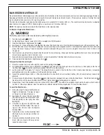
FIGURE 4.2
Summary of Contents for 56303000
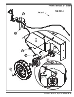
Page 17: ...FORM NO 56043096 Captor 4300B 4800B 15 FRONT WHEEL SYSTEM FIGURE 3 1...
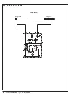
Page 20: ...18 FORM NO 56043096 Captor 4300B 4800B HYDRAULIC SYSTEM FIGURE 4 3...
Page 33: ...FORM NO 56043096 Captor 4300B 4800B 31 SOLUTION SYSTEM FIGURE 7 1...
Page 39: ...FORM NO 56043096 Captor 4300B 4800B 37 SQUEEGEE SYSTEM FIGURE 10 1...
Page 41: ...FORM NO 56043096 Captor 4300B 4800B 39 SQUEEGEE SYSTEM FIGURE 10 2...
Page 45: ...FORM NO 56043096 Captor 4300B 4800B 43 WIRING SCHEMATIC before SN 1767238 ELECTRICAL SYSTEM...
Page 50: ......


